2025-08-21
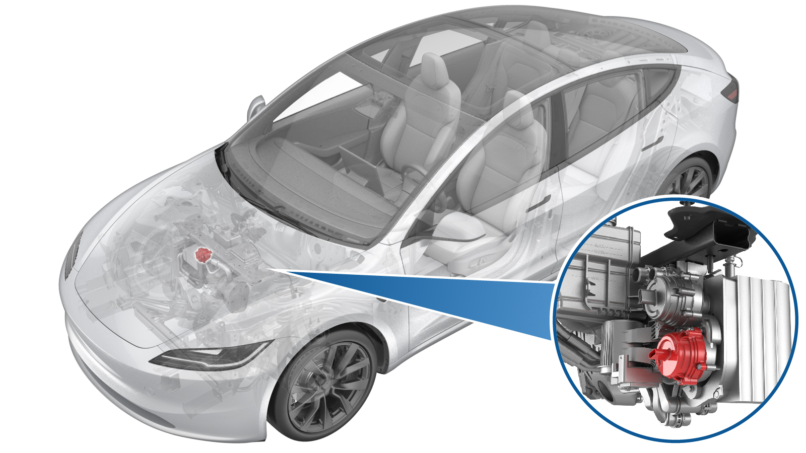
Coolant Pump - HV Battery (Remove and Replace)
 Correction code
1840010162
FRT
0.60
NOTE: Unless otherwise explicitly stated in the procedure, the correction code and FRT listed above reflect all of the work required to perform this procedure, including the linked procedures. Do not stack correction codes unless explicitly told to do so.
NOTE: See Flat Rate Times to learn more about FRTs and how they are created.
NOTE: See Personal Protection to make sure you
are wearing proper PPE when performing the procedure below.
NOTE: See Ergonomic Precautions for safe and healthy working practices.
Correction code
1840010162
FRT
0.60
NOTE: Unless otherwise explicitly stated in the procedure, the correction code and FRT listed above reflect all of the work required to perform this procedure, including the linked procedures. Do not stack correction codes unless explicitly told to do so.
NOTE: See Flat Rate Times to learn more about FRTs and how they are created.
NOTE: See Personal Protection to make sure you
are wearing proper PPE when performing the procedure below.
NOTE: See Ergonomic Precautions for safe and healthy working practices.
- 2024-04-24: Updated the UI routines.
Torque Specifications
| Description | Torque Value | Recommended Tools | Reuse/Replace | Notes |
|---|---|---|---|---|
| Bolts (x4) that attach the HV battery coolant pump to the Supermanifold |
 1.8 Nm (1.3 lbs-ft) |
|
Reuse |
Remove
-
Place the vehicle on the 2-post
lift.
TIpEnsure the vehicle is not charging.
- Open the LH front door and lower the LH front window.
- Remove the rear underhood apron. See Underhood Apron - Rear (Remove and Replace).
- Remove the cabin intake upper duct assembly. See Assembly - Fresh Air Gutter - HVAC (Remove and Replace).
- Enable Service Mode via vehicle touchscreen. See Service Mode.
- Unlock the vehicle gateway. See Gateway Unlock.
- On the touchscreen, touch , click Run, and allow the routine to complete.
- Disconnect LV power. See LV Power (Disconnect and Connect).
- Remove the front aero shield panel. See Panel - Aero Shield - Front (Remove and Replace).
-
Release connector lock, and then
disconnect the HV battery coolant pump electrical connector.
NoteDo not push down on the red tab. Pull the red tab to disengage lock, and then pull again to release the connector.
-
Position a coolant drain container
underneath the battery coolant pump.
-
Remove the bolts (x4) that attach the
HV battery coolant pump to the Supermanifold.
TIpUse of the following tool(s) is recommended:
- Torx T25 socket
- 4 in extension
- Ratchet/torque wrench
-
Remove the HV battery coolant pump
from the Supermanifold.
NoteMake sure both o-rings (inner purple and outer black) come off with old pump.
Install
-
Lubricate both o-rings with silicone o-ring lubricant before installation.
-
Position the HV battery coolant pump
to Supermanifold, and then install and hand tighten the bolts (x4).
NoteTake note of the connector position and install the coolant pump with the connector tab facing up.TIpInstall the upper right bolt with the coolant pump for easier installation.NoteMake sure the coolant pump is fully seated.WarningThe video(s) included in this procedure are meant as an overview for supplemental purposes only. Follow all of the steps listed in the procedure to avoid damage to components and/or personal injury.
-
Torque the bolts (x4) that attach the
HV battery coolant pump to the Supermanifold.1.8 Nm (1.3 lbs-ft)TIpUse of the following tool(s) is recommended:
- Torx T25 socket
- 4 in extension
- Ratchet/torque wrench
-
Connect the HV battery coolant pump electrical connector, and then engage the
connector locking tab.
- Remove the coolant drain container from underneath the vehicle, and clean excess coolant from the area.
- Install the front aero shield panel. See Panel - Aero Shield - Front (Remove and Replace).
- Perform a cooling system vacuum refill. See Cooling System - Vacuum Refill (Test/Adjust).
- Connect LV power. See LV Power (Disconnect and Connect).
- Enable Service Mode Plus. See Service Mode Plus
- Unlock the vehicle gateway. See Gateway Unlock.
-
On the touchscreen, perform the
following steps:
-
Inspect the coolant level, top off as
necessary, and then install the coolant bottle cap.
NoteEnsure that the coolant level is at the "Max" line.
- Install the cabin intake duct assembly. See Assembly - Fresh Air Gutter - HVAC (Remove and Replace).
- Install the rear underhood apron. See Underhood Apron - Rear (Remove and Replace).
- Exit Service Mode. See Service Mode.
- Raise the LH front window and close the LH front door.
- Remove the lift arms from below the vehicle.