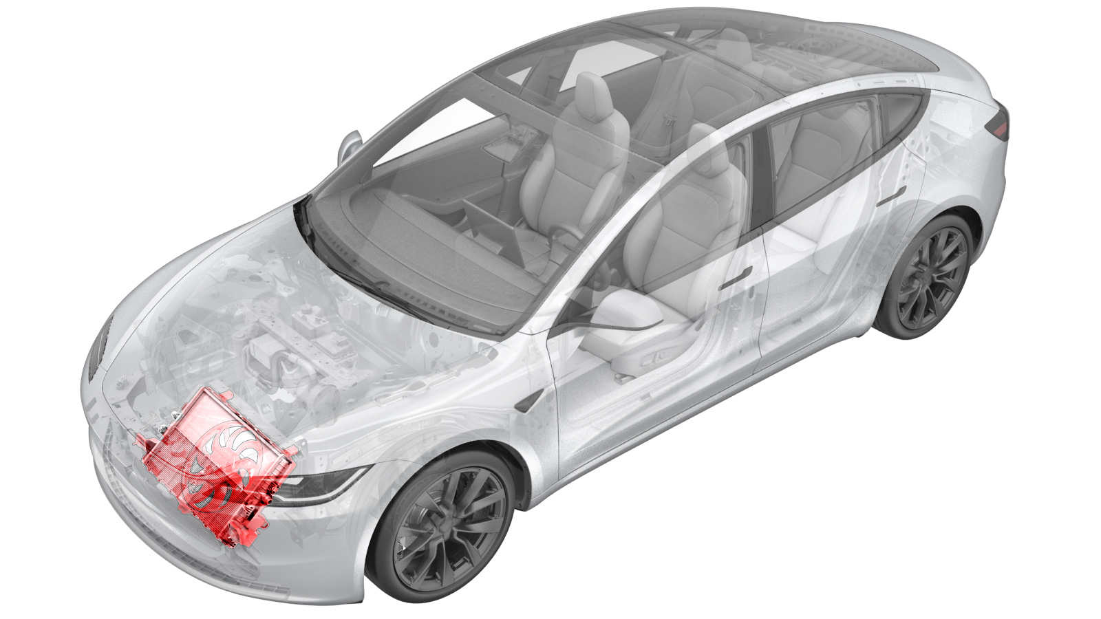
Assembly - Cooling Fan and Shroud (Remove and Replace)
 Correction code
1830010022
FRT
0.84
NOTE: Unless
otherwise explicitly stated in the procedure, the above correction code and
FRT reflect all of the work required to perform this procedure, including
the linked procedures. Do
not stack correction codes unless explicitly told to do so.
NOTE: See Flat Rate
Times to learn more about FRTs and how
they are created. To provide feedback on FRT values, email ServiceManualFeedback@tesla.com.
NOTE: See Personal Protection
to make sure wearing proper PPE when performing the below procedure.
NOTE: See Ergonomic Precautions for safe and
healthy working practices.
Remove
- Remove the active grille shutter. See Active Grill Shutter (Remove and Replace).
-
Release the locking tabs (x2) and
holding mounts (x2) that attach the radiator to the cooling fan and shroud assembly ,
and then remove the radiator from the cooling fan and shroud assembly.
-
Remove the bolts (x2) and isolators
(x2) from the cooling fan and shroud assembly.
Install
-
Install the bolts (x2) and isolators
(x2) from the cooling fan and shroud assembly.
-
Install the radiator to the cooling
fan and shroud assembly, and install the locking tabs (x2) and holding mounts (x2) that
attach the radiator to the cooling fan and shroud assembly.
- Install the active grille shutter. See Active Grill Shutter (Remove and Replace).
-
On the touchscreen, perform the
following steps.
-
Inspect the coolant level and top off
as necessary, and then install the coolant bottle cap.
NoteEnsure that the coolant level is at the "Max" line.
- On the touchscreen, touch and select Run to start the "Thermal System Performance Test" routine, and allow the routine to complete.
- On the touchscreen, touch and select Run to start the "HVAC System Performance Test" routine, and allow the routine to complete.