2025-06-04
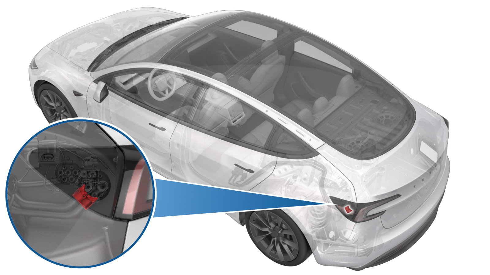
Retainer Bracket - Charge Port (Remove and Replace)
 Correction code
4401010092
FRT
0.72
NOTE: Unless otherwise explicitly stated in the procedure, the correction code and FRT listed above reflect all of the work required to perform this procedure, including the linked procedures. Do not stack correction codes unless explicitly told to do so.
NOTE: See Flat Rate Times to learn more about FRTs and how they are created.
NOTE: See Personal Protection to make sure you
are wearing proper PPE when performing the procedure below.
NOTE: See Ergonomic Precautions for safe and healthy working practices.
Correction code
4401010092
FRT
0.72
NOTE: Unless otherwise explicitly stated in the procedure, the correction code and FRT listed above reflect all of the work required to perform this procedure, including the linked procedures. Do not stack correction codes unless explicitly told to do so.
NOTE: See Flat Rate Times to learn more about FRTs and how they are created.
NOTE: See Personal Protection to make sure you
are wearing proper PPE when performing the procedure below.
NOTE: See Ergonomic Precautions for safe and healthy working practices.
- 2025-06-04: Added instruction to zero adjust the Hioki resistance meter prior to measurement.
Torque Specifications
| Description | Torque Value | Recommended Tools | Reuse/Replace | Notes |
|---|---|---|---|---|
| Nuts (x2) that attach the charge port busbar leads to the charge port studs |
 9 Nm (6.6 lbs-ft) |
|
Reuse |
Remove
- Remove the 3-phase charge port to HV battery busbar safety cap. See Safety Cap - Busbar - Charge Port to HV Battery (3-Phase) (Remove and Replace).
-
Remove the nuts (x2) that
attach the charge port busbar to the charge port and then remove the busbar
leads from the studs.
TIpUse of the following tool(s) is recommended:
- 10 mm deep socket
- Flex head ratchet/flex head torque wrench
- Ratchet/torque wrench
- Electrical Protective Gloves
-
Remove the busbar retainer
bracket.
NoteRelease the 2 tabs and pull up the snap, then slide the bracket out.WarningThe video(s) included in this procedure are meant as an overview for supplemental purposes only. Follow all of the steps listed in the procedure to avoid damage to components and/or personal injury.
Install
-
Install the busbar retainer
bracket.
NoteSlide the bracket in and then press the snap down. Ensure the 2 tabs are installed in place.WarningThe video(s) included in this procedure are meant as an overview for supplemental purposes only. Follow all of the steps listed in the procedure to avoid damage to components and/or personal injury.
-
Use IPA wipes to clean charge port busbar contact surface of the residual
Penetrox.
NoteAllow 1 minute dry time for each surface.
-
Apply 2 drops of Penetrox
A-13 about 5mm in diameter to either side of the hole on both leads on the
HV connector joints, and then spread the liquid evenly until the contact
surface is fully covered.
-
Install the nuts (x2) that
attach the charge port busbar leads to the charge port studs.9 Nm (6.6 lbs-ft)CAUTIONIf excessive force is required to seat busbars, they may have been bent. Inspect for damage and replace if necessary.TIpUse of the following tool(s) is recommended:
- 10 mm deep socket
- Flex head ratchet/flex head torque wrench
- Ratchet/torque wrench
- Electrical Protective Gloves
- Perform zero adjust to Hioki meter. See Resistance Meter (Zero Adjust).
-
Perform Hioki resistance
test at each HV joint from the HV busbar lead to the charge port stud.
NoteThe acceptable resistance is between 0.050 mΩ (50 μΩ) and 0.270 mΩ (270 μΩ).
- If the resistance is greater than 0.270 mΩ (270 μΩ), there is too much resistance in the High Voltage joint. Remove the fastener, clean areas with isopropyl alcohol, install fastener back and test again.
- If the resistance is lower than 0.050 mΩ (50 μΩ), reposition the probes and measure again.
- If the resistance is repeatedly between 0.00 mΩ and 0.050 mΩ (50 μΩ), Hioki test passed, proceed to the next step.
- Install the 3-phase charge port to HV battery busbar safety cap. See Safety Cap - Busbar - Charge Port to HV Battery (3-Phase) (Remove and Replace).