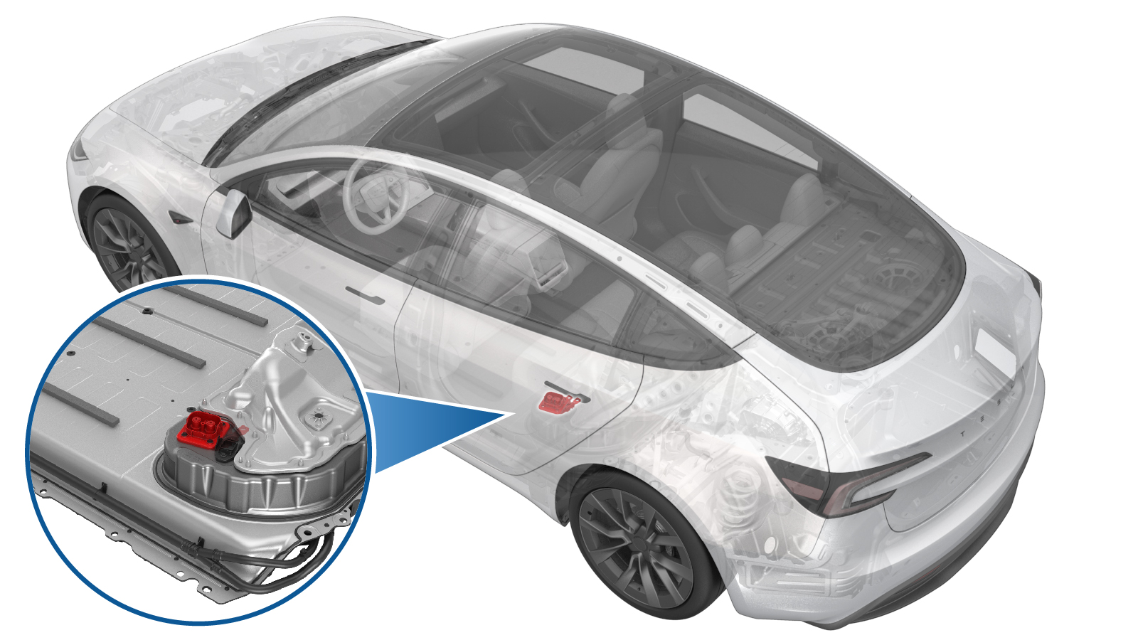
Header - Busbar DC Input (Remove and Replace)
 Correction code
1630010292
FRT
1.26
NOTE: Unless
otherwise explicitly stated in the procedure, the above correction code and
FRT reflect all of the work required to perform this procedure, including
the linked procedures. Do
not stack correction codes unless explicitly told to do so.
NOTE: See Flat Rate
Times to learn more about FRTs and how
they are created. To provide feedback on FRT values, email ServiceManualFeedback@tesla.com.
NOTE: See Personal Protection
to make sure wearing proper PPE when performing the below procedure.
NOTE: See Ergonomic Precautions for safe and
healthy working practices.
- 2025-06-04: Added instruction to zero adjust the Hioki resistance meter prior to measurement, added max. resistance value and updated torque values.
Remove
- Remove the ancillary bay cover. See Ancillary Bay Cover (Remove and Replace).
- Inspect ancillary bay for any missing insulators and install the new insulators if necessary.
-
Remove bolt (X1) securing pyro
disconnect to ancillary bay, and the remove the pyro from ancillary bay.
TIpUse of the following tool(s) is recommended:
- 4 in extension
- 13 mm socket
-
Install pyro disconnect dummy.
-
Disconnect megaharness connector from DC input assembly
-
Remove insulator for DC input assembly to both fastcharge busbar inlet side
-
Remove bolt (X1) securing negative
fastcharge busbar inlet side and negative DC input assembly busbar.
TIpUse of the following tool(s) is recommended:
- 4 in extension
- 13 mm socket
-
Remove bolt securing positive fastcharge busbar inlet side and positive DC input
assembly busbar.
TIpUse of the following tool(s) is recommended:
- 4 in extension
- 13 mm socket
-
Remove bolts securing busbar DC input assembly to ancillary bay.
TIpUse of the following tool(s) is recommended:
- 4 in extension
- 13 mm socket
-
Remove Busbar DC input assembly from ancillary bay.
Install
-
Install Busbar DC input assembly to
ancillary bay.
WarningThe video(s) included in this procedure are meant as an overview for supplemental purposes only. Follow all of the steps listed in the procedure to avoid damage to components and/or personal injury.
-
Install the bolts (x4) securing busbar
DC input assembly to ancillary bay.
 10 Nm (7.4 lbs-ft)TIpUse of the following tool(s) is recommended:
- 4 in extension
-
Install and torque bolt securing
negative fastcharge busbar inlet and negative DC input link to 15 Nm, loosen 180
degrees, and then torque to 5 Nm + 60 degrees.
TIpUse of the following tool(s) is recommended:
- 4 in extension
- 13 mm socket
-
Install and torque bolt securing
positive fastcharge busbar inlet and positive DC input link to 15 Nm, loosen 180
degrees, and then torque to 5 Nm + 60 degrees.
TIpUse of the following tool(s) is recommended:
- 4 in extension
- 13 mm socket
- Perform zero adjust to Hioki meter. See Resistance Meter (Zero Adjust).
-
Perform Hioki resistance test at both HV joints of DC input assembly busbar.
NoteResistance must be 60 𝜇Ω or less. Test from negative fastcharge busbar to negative DC input busbar and positive fastcharge busbar to positive DC input busbar.
-
Install insulator for DC input assembly to both fast charge busbars inlet side.
-
Connect megaharness connector to DC input assembly.
-
Remove pyro disconnect dummy.
- Install the ancillary bay cover. See Ancillary Bay Cover (Remove and Replace).