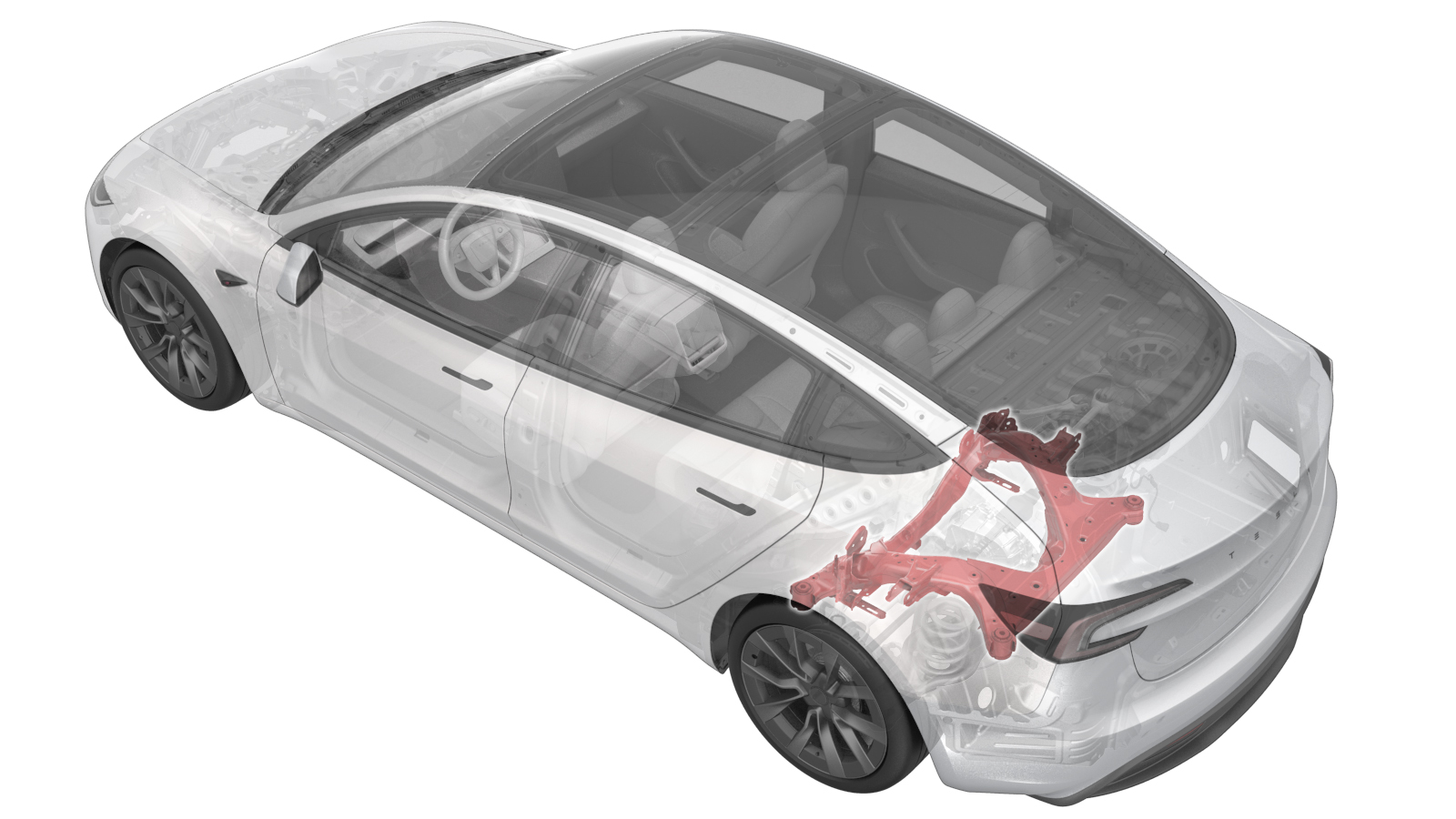
Subframe Assembly - Rear (Remove and Replace)
 Correction code
3001020112
4.38
NOTE: Unless
otherwise explicitly stated in the procedure, the above correction code and
FRT reflect all of the work required to perform this procedure, including
the linked procedures. Do
not stack correction codes unless explicitly told to do so.
NOTE: See Flat Rate
Times to learn more about FRTs and how
they are created. To provide feedback on FRT values, email ServiceManualFeedback@tesla.com.
NOTE: See Personal Protection
to make sure wearing proper PPE when performing the below procedure.
NOTE: See Ergonomic Precautions for safe and
healthy working practices.
Correction code
3001020112
4.38
NOTE: Unless
otherwise explicitly stated in the procedure, the above correction code and
FRT reflect all of the work required to perform this procedure, including
the linked procedures. Do
not stack correction codes unless explicitly told to do so.
NOTE: See Flat Rate
Times to learn more about FRTs and how
they are created. To provide feedback on FRT values, email ServiceManualFeedback@tesla.com.
NOTE: See Personal Protection
to make sure wearing proper PPE when performing the below procedure.
NOTE: See Ergonomic Precautions for safe and
healthy working practices.
- 2024-04-30: Updated the way of performing the routines from using Toolbox to using the touchscreen.
- 1096075-00-A Tool, Hub Puller, Hydraulic
- 1457016-00-A KIT, SPRING COMPRESSOR, GEDORE
- 1135762-00-A Kit, Svc Plug, Cooling Hose, Model 3
- 1130279-00-A Lifting Sling, Drive Unit, Model 3 (NA, APAC)
| Description | Torque Value | Recommended Tools | Reuse/Replace | Notes |
|---|---|---|---|---|
| Nut that secures the rear drive unit ground strap to the vehicle |
 10 Nm (7.4 lbs-ft) |
|
Reuse | |
| Nut that attaches the rear drive unit HV cable bracket to the HV battery |
10 Nm (7.4 lbs-ft) |
|
Reuse | |
| LH and RH rear bolts that attach the subframe to body |
125 Nm (92.2 lbs-ft) |
|
Reuse | |
| LH, RH and rear bolts that attach the drive unit to subframe |
80 Nm (59.0 lbs-ft) |
|
Reuse |
Remove
- Use the hub puller to free the LH and RH halfshafts from the hub splines, then remove the lug nuts and the puller washers from the LH and RH rear rotor studs, and then remove the hub pullers from the rotors. See Halfshaft - Rear Drive Unit - LH (Remove and Replace).
- Open the trunk from an exterior switch.
- Move both front seats forward.
- Place the vehicle in Service Mode by using the touchscreen. See Service Mode.
- Unlock the vehicle gateway. See Gateway Unlock.
- On the touchscreen, tap the Service Mode "wrench" (at the bottom of the touchscreen UI), and then tap , click Run, and then allow the routine to complete.
- On the touchscreen, tap to place the vehicle into tow mode.
- Perform Vehicle HV Disablement Procedure. See Vehicle HV Disablement Procedure (Test/Adjust).
-
Remove the rear fascia. See Fascia Assembly - Rear (Remove and Install).
NoteRemove the rear aero shield instead of partially releasing it. See Panel - Aero Shield - Rear (Remove and Replace).
- Remove the LH and RH rear suspension covers. See Cover - Rear Suspension - LH (Remove and Replace).
-
Remove and discard the bolts (x2) that attach the LH rear caliper to the LH rear knuckle, remove the caliper from the knuckle, and allow the caliper to hang from an S-hook.
TIpUse of the following tool(s) is recommended:
- Cordless Ratchet/Impact Driver
- External Torx E18
- 3 in extension
- Ratchet/torque wrench
-
Install spring compressor onto the LH
rear coil spring.
NoteTooling may vary per service center.TIpUse of the following tool(s) is recommended:
- Ratchet/torque wrench
- 19 mm deep socket
- 1096075-00-A Tool, Hub Puller, Hydraulic
-
Remove the bolt that
attaches the LH rear damper to the lower aft link.
NoteUse of the following tool(s) is recommended:
- Cordless Ratchet/Impact Driver
- 21 mm socket
- Repeat step 11 to 13 for the RH side.
-
Remove the nut that secures the rear
drive unit ground strap to the vehicle.
TIpUse of the following tool(s) is recommended:
- Ratchet/torque wrench
- 10 mm 12-point deep socket
-
Raise the vehicle to a comfortable
working height, and lower the lift onto locks.
CAUTION
Make sure there is an audible click of the locks on both sides before lowering, otherwise the vehicle may tilt to one side.
Make sure that the doors are clear of surrounding objects.
-
Disconnect the RH side subframe
harness connector.
-
Remove the RH side subframe harness
clips (x2) from body.
- Remove the rear stabilizer bar assembly. See Stabilizer Bar - Rear (Remove and Replace).
-
Release clips (x4) that secure the
coolant hoses to LH and RH shear plates.
Figure 1. LH Shown, RH Similar - Remove the rear skid plate. See Skid Plate - HV Battery - Rear (Remove and Replace).
- Position a coolant drain container underneath the RH rear of the vehicle.
-
Release the push clips (x2) that
attach the RH rear wheel liner to rocker panel, and move the wheel liner aside for
access.
-
Disconnect the rear drive unit outlet
hose from powertrain return tube and plug both hose ends.
NoteLower the hose located at the RH rear of HV battery. Use a shop towel to clean any residue coolant if necessary. Coolant loss greater than 1L requires vacuum fill.
- Remove the rear drive unit inverter inlet hose. See Hose - Inlet - Rear Drive Unit Inverter (Remove and Replace).
- Remove the coolant drain container from underneath the vehicle.
-
Remove the nut that attaches the rear
drive unit HV cable bracket to the HV battery.
NoteThe number of fasteners may vary.TIpUse of the following tool(s) is recommended:
- 10mm Magnetic Deep Nutsetter
- Cordless Ratchet/Impact Driver
- 10 mm socket
- Ratchet/torque wrench
-
Disconnect the connector that attach
the rear drive unit HV cable to the HV battery.
NoteRelease the locking tab and rotate the release lever up to disengage the connector. Do not force the release lever up. Ensure the alignment tabs on the rear drive unit header are not damaged.
- Place the subframe lifting tool underneath the rear subframe, and connect air supply to the tool.
-
With assistance, raise the subframe
lifting tool to support the rear subframe.
NoteAttach metal hooks at the end of straps to rings on subframe lifting tool and pull the straps until secure. Lower the vehicle if necessary.
-
Mark the LH and RH rear subframe bolts
(x2).
NoteMark the original location of the subframe in order to re-align during install. Also mark the subframe casting and the subframe bushing to body if needed.
- Remove the LH and RH rear subframe shear plates. See Shear Plate - Rear Subframe - LH (Remove and Replace).
-
Remove and discard the LH and RH rear
bolts that attach the subframe to body.
TIpUse of the following tool(s) is recommended:
- Ratchet/torque wrench
- 6 in extension
- 21 mm socket
-
Lower the subframe and rear drive unit
assembly from the vehicle.
CAUTIONUse caution while lowering the subframe to avoid damage to surrounding components.
- Disconnect air supply from the subframe lifting tool, and then move the subframe lifting tool and subframe away from the vehicle.
-
Remove the LH and RH rear coil springs
from the rear lower aft link.
-
Release the rear drive unit ground
strap clip from subframe.
-
Position the fluid catcher under the
subframe and fixture assembly.
NoteUse a foldable funnel as required for the next steps.
-
Release the rear drive unit logic
connection clip.
-
Release the rear drive unit logic
connector.
NoteRelease the locking tab then push the handle downward to release the connector.
-
Disconnect the resolver
connector.
-
Release the clips (x2) from the rear
drive unit.
-
Disconnect the oil pump
connector.
-
Release the clips (x8) that attach the subframe harness to the top rear of subframe,
and then remove the harness.
- Remove the LH and RH rear halfshafts. See Halfshaft - Rear Drive Unit - LH (Remove and Replace).
- Remove the LH and RH rear knuckles. See Knuckle - Rear - LH (Remove and Replace).
- Remove the LH and RH rear upper aft links. See Link - Aft - Upper - Rear - LH (Remove and Replace).
- Remove the LH and RH rear upper fore links. See Link - Fore - Upper - Rear - LH (Remove and Replace).
- Remove the LH and RH rear toe links. See Toe link - Rear - LH (Remove and Replace).
- Remove the LH and RH rear lower fore links. See Link - Fore - Lower - Rear - LH (Remove and Replace).
- Remove the LH and RH rear lower aft links. See Link - Aft - Lower - Rear - LH (Remove and Replace).
- Position the rear subframe assembly under the gantry.
-
Attach drive unit sling tools to the
drive unit.
-
Secure the drive unit sling to the
gantry, and raise the sling until there is slight tension on the cables.
-
Remove the LH, RH,and rear bolts that
attach the drive unit to the subframe.
TIpUse of the following tool(s) is recommended:
- Ratchet/torque wrench
- 18 mm socket
Figure 2. LH Shown, RH Similar Figure 3. Rear Bolt - Move the subframe and lifting tool from underneath the drive unit.
-
Position an empty drive unit crate
below the drive unit.
NoteUse a pallet if no empty crate is available.
-
Lower the drive unit into the drive
unit crate.
-
With assistance, release the straps to
remove the subframe from the lifting tool.
Install
- With assistance, install a new subframe onto lifting tool and secure the straps.
- Raise the drive unit out of the drive unit crate.
- Move the subframe and lifting tool to underneath the drive unit.
-
With assistance, lower the sling to
install the drive unit into subframe.
-
Hand tighten the bolts (x3) that
attach the drive unit to subframe.
Figure 4. LH Shown, RH Similar Figure 5. Rear Bolt - Lower the sling to release tension on the cables.
-
Torque the bolts (x3) that attach the
drive unit to subframe.80 Nm (59.0 lbs-ft)TIpUse of the following tool(s) is recommended:
- Ratchet/torque wrench
- 18 mm socket
- Release the drive unit sling tool from the rear drive unit.
- Move the subframe assembly away from under the gantry.
- Install the LH and RH rear lower aft links. See Link - Aft - Lower - Rear - LH (Remove and Replace).
- Install the LH and RH rear lower fore links. See Link - Fore - Lower - Rear - LH (Remove and Replace).
- Install the LH and RH rear toe links. See Toe link - Rear - LH (Remove and Replace).
- Install the LH and RH rear upper fore links. See Link - Fore - Upper - Rear - LH (Remove and Replace).
- Install the LH and RH rear upper aft links. See Link - Aft - Upper - Rear - LH (Remove and Replace).
- Install the LH and RH rear knuckles. See Knuckle - Rear - LH (Remove and Replace).
-
Install the LH and RH rear halfshafts.
See Halfshaft - Rear Drive Unit - LH (Remove and Replace).
NotePause before installing the hub jack adapter.
-
Install the subframe harness into
position, and then secure the clips (x8) along the top rear of subframe.
-
Connect the oil pump connector.
-
Secure the clips (x2) onto the rear
drive unit.
-
Connect the resolver connector.
-
Connect the rear drive unit logic
connector.
-
Secure the rear drive unit logic
connection clip.
-
Secure the rear drive unit ground
strap clip onto the subframe.
-
Position LH and RH rear coil springs
on the LH and RH rear lower aft links.
NoteMake sure the coil springs are positioned against the stops on the rear lower aft links.
- Position the subframe and rear drive unit assembly under the vehicle, and then connect air supply to the subframe lifting tool.
-
Raise the subframe and rear drive unit
assembly into position.
CAUTIONUse caution to not damage components while raising the subframe.
-
Hand tighten the LH and RH rear bolts
that attach the rear subframe to body.
Figure 6. LH Shown, RH Similar - Install the LH and RH rear subframe shear plates. See Shear Plate - Rear Subframe - LH (Remove and Replace).
-
Position the subframe to the marked
location.
NoteUse previous markings to align the subframe to body. Return the subframe to original position as close as possible.
-
Torque the LH and RH rear bolts that
attach the subframe to body.125 Nm (92.2 lbs-ft)NoteMark the bolts after torque.TIpUse of the following tool(s) is recommended:
- Ratchet/torque wrench
- 6 in extension
- 21 mm socket
Figure 7. LH Shown, RH Similar -
Lower the rear subframe lifting tool
from the vehicle.
NoteVerify the yellow safety straps are removed from the subframe.
- Disconnect the air supply from the subframe lifting tool, and remove the subframe lifting tool from underneath vehicle.
-
Connect the connector that attaches
the rear drive unit HV cable to the HV battery.
NoteMake sure the connector lock is 90 degrees from the connector before beginning to secure the connector. Use one hand to support the connector while the other hand latching the locking tab. Once installed, verify that the latch is not damaged and fully secured in the latched position.
-
Install nut that attaches the rear
drive unit HV cable bracket to the HV battery.10 Nm (7.4 lbs-ft)NoteNumber of fasteners may vary.TIpUse of the following tool(s) is recommended:
- 10mm Magnetic Deep Nutsetter
- Cordless Ratchet/Impact Driver
- 10 mm socket
- Ratchet/torque wrench
- Position the coolant drain container underneath the LH rear drive unit area.
- Install the rear drive unit inverter inlet hose. See Hose - Inlet - Rear Drive Unit Inverter (Remove and Replace).
- Position coolant drain container underneath the RH rear of vehicle.
-
Install the rear drive unit outlet
hose to the powertrain return tube.
NotePerform a push-pull-push test to make sure the hose is fully engaged. Clean excess coolant from area.
-
Secure the push clips (x2) that attach
the RH rear wheel liner to the rocker panel.
- Remove the coolant drain container from underneath vehicle.
- Install the rear skid plate. See Skid Plate - HV Battery - Rear (Remove and Replace).
-
Install fir free clips (x4) that
attach the coolant hoses to the LH and RH shear plates.
Figure 8. LH Shown, RH Similar - Install the rear stabilizer bar assembly. See Stabilizer Bar - Rear (Remove and Replace).
-
Hand-tighten the bolt that
attaches the LH rear damper to the lower aft link.
NoteThe fasteners are fully tightened in a later step.
- Repeat last step for the RH side.
-
Install the clips (x2) that attach the
RH side subframe harness to body.
-
Connect the RH side subframe harness
connector.
- Lower the vehicle to a comfortable working height and set the lift onto locks.
-
Install the nut that secures the rear
drive unit ground strap to the vehicle.10 Nm (7.4 lbs-ft)NoteRe-install a washer if vehicle had this washer during removal.TIpUse of the following tool(s) is recommended:
- Ratchet/torque wrench
- 10 mm 12-point deep socket
-
Install new bolts (x2) that attach the LH rear caliper to the LH rear knuckle.83 Nm (61.2 lbs-ft)TIpUse of the following tool(s) is recommended:
- Cordless Ratchet/Impact Driver
- External Torx E18
- 3 in extension
- Ratchet/torque wrench
CAUTIONTo prevent damage to the flexible brake hose, make sure that the brake hose is not twisted and can bend forward and does not make contact with the wheel arch liner when the vehicle is lowered. - Fully install the LH and RH rear halfshafts. See Halfshaft - Rear Drive Unit - LH (Remove and Replace).
- Install LH and RH suspension covers. See Cover - Rear Suspension - LH (Remove and Replace).
-
Install the rear fascia. See Fascia Assembly - Rear (Remove and Install).
NoteFully install the rear aero shield. See Panel - Aero Shield - Rear (Remove and Replace).
- Install all the four wheels. See Wheel Assembly (Remove and Install).
- Install the 2nd row seat cushion. See Seat Cushion - 2nd Row (Remove and Replace).
- Perform a cooling system vacuum refill. See Cooling System - Vacuum Refill (Test/Adjust).
- Install the cabin intake duct. See Assembly - Fresh Air Gutter - HVAC (Remove and Replace).
- Install the rear underhood apron. See Underhood Apron - Rear (Remove and Replace).
- Move both front seats to original position.
- Hold the brake pedal and tap Transport Mode on the touchscreen to disable the EPB service mode.
- Exit Service Mode. See Service Mode.
- Close the trunk by using interior switch.
- Raise all windows and close all doors.
- Remove the lift arms from below the vehicle.
- Refer to the Alignment Requirement tables to determine whether an EPAS alignment check (EC) or four wheel alignment check (AC) is necessary. If performed, add the alignment check/adjust as a separate activity. See Alignment Requirement - Suspension.