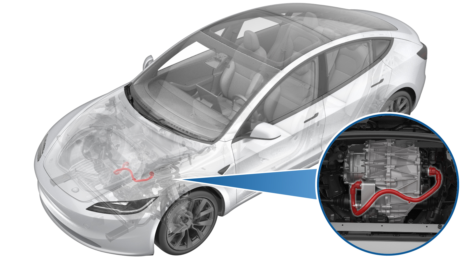
Hose - Front Drive Unit to Oil Cooler (Remove and Replace)
 Correction code
1830020122
FRT
0.42
NOTE: Unless
otherwise explicitly stated in the procedure, the above correction code and
FRT reflect all of the work required to perform this procedure, including
the linked procedures. Do
not stack correction codes unless explicitly told to do so.
NOTE: See Flat Rate
Times to learn more about FRTs and how
they are created. To provide feedback on FRT values, email ServiceManualFeedback@tesla.com.
NOTE: See Personal Protection
to make sure wearing proper PPE when performing the below procedure.
NOTE: See Ergonomic Precautions for safe and
healthy working practices.
Correction code
1830020122
FRT
0.42
NOTE: Unless
otherwise explicitly stated in the procedure, the above correction code and
FRT reflect all of the work required to perform this procedure, including
the linked procedures. Do
not stack correction codes unless explicitly told to do so.
NOTE: See Flat Rate
Times to learn more about FRTs and how
they are created. To provide feedback on FRT values, email ServiceManualFeedback@tesla.com.
NOTE: See Personal Protection
to make sure wearing proper PPE when performing the below procedure.
NOTE: See Ergonomic Precautions for safe and
healthy working practices.
- 1135762-00-A Kit, Svc Plug, Cooling Hose, Model 3
- 1080568-00-A Fluid Catcher
- 1065131-00-A Battery Coolant Drain Kit
Remove
- Raise and support the vehicle. See Raise Vehicle - 2 Post Lift.
- Disconnect the LV power. See LV Power (Disconnect and Connect).
- Remove the underhood storage unit. See Underhood Storage Unit (Remove and Replace).
-
Raise the vehicle fully and lower the lift onto locks.
CAUTION
Make sure there is an audible click of the locks on both sides before lowering, otherwise the vehicle may tilt to one side.
Make sure that the doors are clear of surrounding objects.
- Remove the front aero shield panel. See Panel - Aero Shield - Front (Remove and Replace).
-
Position a coolant drain container underneath LH front of the HV battery.
-
Disconnect the front drive unit inverter inlet hose from the fluid coupling, and plug
the ends of both fittings as soon as possible to avoid coolant loss.
NoteCoolant loss greater than 1L requires vacuum fill.
-
Position the coolant drain underneath RH front of the front drive unit.
-
Disconnect the front drive unit inverter inlet hose from the heat exchanger, and plug
the ends of both fittings as soon as possible to avoid coolant loss.
NoteCoolant loss greater than 1L requires vacuum fill.
- Remove the coolant drain container from underneath the vehicle.
- Raise the lift off locks, hold the lock release lever to keep locks free while the vehicle is lowered, and then set the vehicle to a comfortable working height, then set the lift onto locks.
-
Release the inverter to oil cooler hose clip, and then remove the inverter to oil
cooler hose from the front drive unit.
Install
-
Install the inverter to oil cooler hose to the front drive unit by securing the
inverter to oil cooler hose clip.
-
Raise the vehicle fully and lower the lift onto locks.
CAUTION
Make sure there is an audible click of the locks on both sides before lowering, otherwise the vehicle may tilt to one side.
Make sure that the doors are clear of surrounding objects.
-
Position a coolant drain container
underneath the LH front of the HV battery.
-
Remove the plugs from the ends of both fittings, and then connect the front drive
unit inverter inlet hose to the fluid coupling.
Note
Perform a push-pull-push test to make sure the hose is fully engaged. Coolant loss greater than 1L requires vacuum fill.
-
Position the coolant drain underneath
the RH front of the front drive unit.
-
Remove the plugs from the ends of both fittings, and then connect the front drive
unit inverter inlet hose to the heat exchanger.
Note
Perform a push-pull-push test to make sure the hose is fully engaged. Coolant loss greater than 1L requires vacuum fill.
- Remove the coolant drain container from underneath the vehicle.
- Install the front aero shield panel. See Panel - Aero Shield - Front (Remove and Replace).
- Raise the lift off locks, hold the lock release lever to keep locks free while the vehicle is lowered, and then fully lower the vehicle.
- Connect the LV power. See LV Power (Disconnect and Connect).
-
Remove the coolant cap and fill the coolant to MAX line.
- Unlock the gateway. See Gateway Unlock.
-
Tap the Service Mode "wrench" (at the
bottom of the touchscreen UI), and then tap to perform the Coolant Air Purge.
Note
- Make sure that the vehicle is not in Drive. Putting the vehicle into Drive will stop this routine.
- The pumps will still run for some time after the Routine Passed message displays. Do not start another routine before the coolant pumps stop running.
- The speed in the test varies from 3500-6500 RPM (idle speed = ~1500 RPM) and the actuated valve varies between SERIES and PARALLEL.
- If the speed hovers at 7000 RPM, it indicates the pumps are air locked. Perform the vacuum fill again. Continue to add the coolant and purge until the coolant level reaches between the NOM and MAX Lines on the bottle.
- Inspect the coolant level and top off as necessary, make sure that the fluid level is at the MAX line, and then install the coolant bottle cap.
- Install the underhood storage unit. See Underhood Storage Unit (Remove and Replace).
- Install the rear underhood apron. See Underhood Apron - Rear (Remove and Replace).
- Raise the LH front window and close the LH front door.
- Remove the lift arms from below the vehicle.