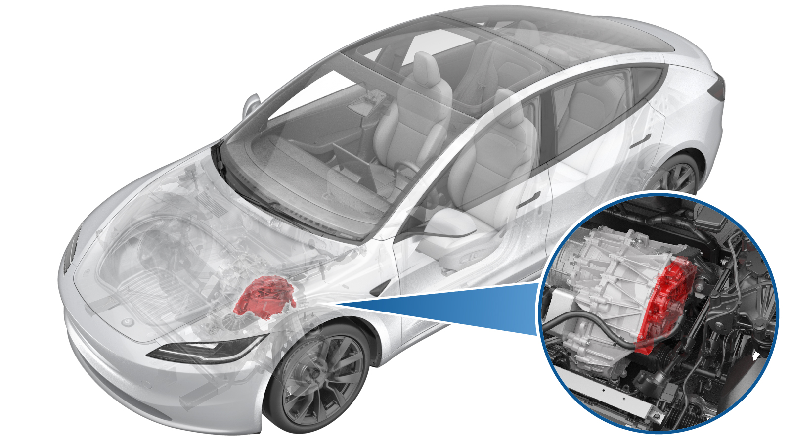
Inverter - Front Drive Unit (3DU) (Remove and Replace)
 Correction code
3920010012
FRT
3.54
NOTE: Unless otherwise explicitly stated in the procedure, the correction code and FRT listed above reflect all of the work required to perform this procedure, including the linked procedures. Do not stack correction codes unless explicitly told to do so.
NOTE: See Flat Rate Times to learn more about FRTs and how they are created.
NOTE: See Personal Protection to make sure you
are wearing proper PPE when performing the procedure below.
NOTE: See Ergonomic Precautions for safe and healthy working practices.
Correction code
3920010012
FRT
3.54
NOTE: Unless otherwise explicitly stated in the procedure, the correction code and FRT listed above reflect all of the work required to perform this procedure, including the linked procedures. Do not stack correction codes unless explicitly told to do so.
NOTE: See Flat Rate Times to learn more about FRTs and how they are created.
NOTE: See Personal Protection to make sure you
are wearing proper PPE when performing the procedure below.
NOTE: See Ergonomic Precautions for safe and healthy working practices.
Remove
- Verify that the vehicle firmware is version feature/poppyseed-32-5 or later. Update the vehicle software if this is not the case.
- Raise and support the vehicle. See Raise Vehicle - 2 Post Lift.
- Open all doors and lower all windows.
- Move both front seats forward.
-
Connect a laptop with Toolbox to the
vehicle. See Toolbox (Connect and Disconnect).
NoteUpon successful connection, Service Mode Plus will be enabled, and the "Service Mode Plus" watermark will appear on the touchscreen.
- Enable Service Mode Plus. See Service Mode Plus.
- On the touchscreen, touch .
- Run PROC_PMF_X_STORE-DATA-BOOTvia Service Mode Plus:Drive Inverter ➜ Front Drive Inverter Replacement ➜ Store Bootloader Datavia Toolbox:(link)
- Run PROC_DIF_X_STORE-DATA-APPvia Service Mode Plus:Drive Inverter ➜ Front Drive Inverter Replacement ➜ Store Application Datavia Toolbox:(link)
- Run PROC_VCFRONT_X_START-THERMAL-FILL-DRAIN-COOLANTvia Toolbox:(link)
- Disconnect the laptop with Toolbox from the vehicle. See Toolbox (Connect and Disconnect).
- Disconnect the LV battery power. See LV Power (Disconnect and Connect).
- Remove the underhood storage unit. See Underhood Storage Unit (Remove and Replace).
- Perform the Vehicle HV Disablement Procedure. See Vehicle HV Disablement Procedure (Test/Adjust).
-
Set the steering wheel straight
ahead.
-
Lock the steering wheel into
position.
-
Remove bolt securing steering column
to steering gear assembly
Note1x bolt, 13mm, 18 Nm, Discard fastener after removal
-
Disconnect steering column from
steering gear assembly
NoteSlide steering column upward from steering gear assembly to disconnect, pictures are shown for clarity of how to disconnect steering column from steering gear
-
Release connection for FDU front
subframe harness
Note1x locking connector, Release the grey locking tab then press on the tab to release the connector
-
Disconnect steering gear assembly
connectors
Note4x connectors, Release locking tabs
- Remove both front wheels. See Wheel Assembly (Remove and Install).
- Remove the front fascia. See Fascia - Front (Remove and Install).
- Remove the front aero shield panel. See Panel - Aero Shield - Front (Remove and Replace).
-
Remove bolt securing RH front wheel
liner to skid plate.
Note1x bolt, 10mm, 5 Nm
-
Remove push clips securing lower rear
edge of RH front wheel liner to vehicle for access to coolant hose
Note3x push clips
-
Remove both LH and RH bolts securing
wheel liners to front skid plate
Note2x blots, 10mm, 5 Nm
-
Remove front skid plate
Note4x bolts, EP10, 13 Nm, 2x tabs, Move forward to remove
-
Remove bolt securing FDU HV harness to
FDU
Note1x bolt, 10mm, 10 Nm
-
Disconnect FDU HV harness
connector
Note1x clip, Release locking tab and rotate the release lever up to disengage the connector, Do not force the release lever up, Ensure the alignment tabs on the FDU header are not damaged
-
Remove bolt securing FDU ground strap
to FDU
Note1x bolt, 10mm, 6 Nm
-
Release FDU ground strap harness clip
from FDU
Note1x clip
-
Position coolant drain container
underneath RH front of HV battery
-
Disconnect PT return tube from FDU
inverter inlet hose
Note1x spring clip, 2x plugs, Plug hose end and fluid coupling
-
Position coolant drain underneath RH
front of FDU
-
Disconnect FDU PT return hose from FDU
heat exchanger
Note1x spring clip, 2x plugs, Plug heat exchanger and FDU PT return hose end as quickly as possible to avoid coolant loss. Coolant loss greater than 1 L will require vacuum fill
- Remove the coolant drain container from underneath the vehicle.
-
Lower vehicle partially and set lift
onto locks
NoteRaise lift off locks, Then hold lock release lever to keep locks free while vehicle is lowered, Set vehicle to comfortable working height
-
Release bolt securing LH front brake
hose bracket to knuckle
Note1x bolt, 10mm, 5 Nm
-
Release bolt securing LH front wheel
speed sensor to knuckle
Note1x bolt, T30, 5 Nm
-
Release LH front wheel speed sensor
harness from knuckle
Note2x clips,Sensor removed to one side
-
Remove LH front brake caliper from
knuckle
Note2x bolts, E18, 94 Nm, Discard fasteners after removal, Hang caliper off to the side with S-hook
-
Remove nut securing front stabar end
link to LH front strut and separate
Note1x nyloc nut, 18mm, 98 Nm, Counter hold ball joint with T40, Discard fastener after removal, Separate end link from the strut, If required a pry bar can be used to relieve tension
-
Remove nut and bolt securing LH front
upper control arm to knuckle
Note1x bolt, T50, 1x nyloc nut, 15mm, 56 Nm, Discard nut after removal, Release nut and compress ball joint downwards to release bolt
-
Remove bolt and nut securing LH strut
to lower fore link
Note1x bolt, 21mm, 1x nut, 21mm, 106 Nm
-
Release bolt securing RH front wheel
speed sensor to knuckle
Note1x bolt, 10mm, 5 Nm
-
Release RH front wheel speed sensor
harness from knuckle and move aside
Note2x harness clips
-
Release bolt securing RH front brake
hose bracket to knuckle
Note1x bolt, 10mm, 5 Nm
-
Release RH front brake caliper from RH
front knuckle
Note2x bolts, E18, 94 Nm, Discard fasteners after removal, Hang caliper off to the side with S-hook
-
Release nut securing front stabar end
link to RH front strut and separate
Note1x nyloc nut, 18mm, 98 Nm, Counter hold ball joint with T40, Discard fastener after removal, Separate end link from the strut
-
Release nut and bolt securing RH front
upper control arm to knuckle
Note1x bolt, T50, 1x nyloc nut, 15mm, 56 Nm, Discard nut after removal, Release nut and compress ball joint downwards to release bolt
-
Release nut and bolt securing RH strut
to RH front lower lateral link
Note1x bolt, 21mm, 1x nut, 21mm, 106 Nm
-
Raise the vehicle to a comfortable
working height, and lower the lift onto locks.
CAUTION
Make sure there is an audible click of the locks on both sides before lowering, otherwise the vehicle may tilt to one side.
Make sure that the doors are clear of surrounding objects.
-
Position powertrain subframe lift
underneath front of vehicle
-
Connect air supply to subframe lifting
tool
-
Raise powertrain table and subframe
fixture into position
Note2x subframe datums, 1x FDU datum, Raise fixture until the front subframe is fully supported, Line up the two subframe datums and support arms, Continue to line up the FDU datum and FDU support arm, Raise and adjust arms as needed,
-
Fully secure straps from fixture onto
front subframe
-
Remove bolts securing front end
carrier to LH front subframe crash can assembly
Note2x bolts, 13mm, 16 Nm
-
Remove bolts securing front end
carrier to RH front subframe crash can assembly
Note2x bolts, 13mm, 16 Nm
-
Remove bolt securing RH motor mount to
RH motor mount bracket
Note1x bolt, E18, 105 Nm
-
Remove bolt securing LH motor mount to
LH motor mount bracket
Note1x bolt, E18, 105 Nm
-
Remove bolts securing front subframe
mid mounts to body
Note2x bolts, 15mm, 50 Nm, Discard after removal
-
Remove bolts securing front portion of
front subframe to body
Note2x bolts, 18mm, 72 Nm, Discard after removal
-
Remove smaller bolts securing rear
portion of front subframe to body
Note2x bolts, 15mm, 50 Nm, Discard after removal
-
Remove larger bolts securing rear
portion of front subframe to body
Note2x bolts, 21mm, 125 Nm, Discard after removal
-
Lower front subframe assembly and
front unit assembly from vehicle
NoteKeep an eye out for any components that could get caught while lowering
-
Disconnect air supply from subframe
lifting tool
-
Remove subframe lifting tool from
under vehicle
-
Position fluid catcher under subframe
and fixture assembly
NotePosition to catch all coolant loss, Use a foldable funnel as required for the next steps
-
Release FDU inverter to oil cooler
hose from the heat exchanger
Note1x hose clip, Use a foldable funnel as required
-
Release FDU inverter to oil cooler
hose from inverter fluid coupling
Note1x hose clip, Use a foldable funnel as required
-
Release inverter to oil cooler hose
clip from FDU
-
Remove inverter to oil cooler hose
from FDU
NoteRemove coolant plugs from each hose end if discarding
-
Release FDU inverter inlet hose from
90deg fluid coupling
Note1x spring clip, Use a foldable funnel as required
-
Release clips securing FDU inverter
inlet hose and remove hose
Note2x clips
-
Disconnect FDU inverter logic
connector
Note1x connector, Release locking tab then push handle downward
-
Release the FDU harness clips (x2)
from the inverter housing
-
Remove front drive unit LH mount from
front drive unit
Note3x bolts, E14, 35 Nm + 55 degrees, Discard after removal
-
Attach an Electrostatic Discharge
(ESD) wrist strap to the front drive unit inverter housing.
-
Remove label from phase cover
NoteDiscard label after removal
-
Remove bolts securing phase out
cover
Note2x bolts, EP10, 14 Nm
-
Remove phase out cover
NoteUse a plastic trim tool to aid in removal, If phase out cover or O-rings are damaged then replace with a new unit
-
Release fasteners securing inverter to
the 3 phase lugs
Note3x bolts, 10mm, 11.5 Nm, Do not drop fasteners, Fasteners can be re-used
-
Remove bolts securing the FDU inverter
to gearbox assembly
Note12x bolts, EP10, 12.5 Nm, Fasteners can be re-used
-
Remove inverter and gasket from drive
unit
Note1x gasket, Carefully remove inverter, Take care and do not damage the circuit board when handling, Drain inverter of coolant, Do not damage or place face down on HV lugs, Careful not to damage the PCBA during removal
-
Place drive inverter on ESD mat
NoteCarefully place inverter on ESD safe mat, Do not place inverter facing downwards on the circuit board as it is fragile, Do not damage or place face down on HV lugs, Careful not to damage the PCBA during removal
-
Remove ESD wrist strap from
inverter
-
If the pyrotechnic fuse of the drive
unit inverter has not been actuated, dispose of the drive unit inverter as hazardous
material. If the pyrotechnic fuse has been actuated, follow the normal regulations for
waste disposal.
NoteIf Autodiag falsely indicated that the pyrotechnic fuse was actuated, but visual check confirms that it was not activated, list the serial number of the drive unit inverter in Autodiag using 'Report an Issue'.
Install
-
Prepare new drive inverter
NotePrepare new drive inverter, Save packaging to MRB old drive inverter, Remove any red protective covers,Refer to https://toolbox.teslamotors.com/articles/6865600 for instruction of installing 2PO inverter to the 3DU vehicle
-
Secure ESD strap to new inverter
housing
-
Clean mating surfaces of phase lugs
NoteClean with IPA, Allow 1 min to dry, Do not leave any debris on the mating surfaces
-
Inspect gap pad of the new
inverter
NoteVerify the gap pad is fully attached and covering the discharge resistor array, No resistors should be visible, Gap pad should be clean of debris and evenly adhered. Replace gap pad if it does not match the criteria
-
Position inverter with gasket to drive
unit
Note1x gasket, 2x guide pins, Make sure the 3 phase cables and guides align during installation
-
Install fasteners securing inverter to
gearbox assembly
Note12x bolts, EP10, 12.5 Nm, Install hand tight, Install new fasteners, Torque at a later step
-
Torque fasteners securing FDU inverter
to FDU
Note12x bolts, EP10, 12.5 Nm, Torque two fasteners nearest alignment dowels first
-
Install fasteners securing inverter to
the 3 phase lugs
Note3x bolts, 10mm, 11.5 Nm, Fasteners can be re-used, Do not drop fasteners, Use a magnet as needed, If re-using fastener torque to 11.5 Nm. If installing new fasteners torque to 12.5 Nm, Reverse 180 degrees, then torque to 5 Nm + 40 degrees, With new fasteners, perform run down sequence to prevent under torque
-
Install phase out cover
NoteIf phase out cover or O-rings are damaged then replace with a new unit, Fully seat cover
-
Install bolts securing phase out
cover
Note2x bolts, EP10, 14 Nm
-
Install new 3 phase access label
NoteVerify label is properly seated
-
Remove ESD wrist strap from
inverter
-
Take old inverter and prepare for MRB,
Label properly for return or disposal
NoteUse ESD wrist strap, Label inverter for MRB and return to packaging, Secure any protective red caps, Return or dispose of packaging through proper channels, Label the part as MRB
-
Install leak test adapter plug to 12V
connector at inverter
-
Install leak test adapter to HV
connector
-
Connect regulator to adapter at HV
connector
-
Close both valves on the regulator
test tool
-
Connect regulator to air supply
-
Turn on regulator and open valve
closest to regulator
-
Set regulator to 1 psi
-
Open 2nd valve to inject air into
penthouse
NoteClose valve when pressure reaches 1 psi and stable
- Wait 45 seconds for pressure to settle
- Record start pressure valve
- Wait 60 seconds for test
-
Record end pressure valve
NoteIf pressure did not drop more than 0.04 psi, continue to next step. If pressure dropped more than 0.04 psi, then inspect for leaks.
-
Disconnect air supply from regulator
tool
-
Disconnect regulator from leak test
adapter at HV connector
-
Remove leak test adapter from HV
connector
-
Remove leak test adapter plug from 12V
connector at inverter
-
Install the front drive unit LH mount
to the front drive unit
Note3x bolts, E14, 35 Nm + 55 degrees, Install new bolts
-
Secure FDU harness clips (x2) onto the
inverter housing.
-
Connect FDU inverter logic
connector.
NoteFully seat connector then secure locking tab
-
Position FDU inverter inlet hose and
remove hose and secure clips
Note2x clip
-
Secure FDU inverter inlet hose to
90deg fluid coupling
Note1x hose clip, Perform push-pull-push test
-
Install inverter to oil cooler hose
onto FDU
Note1x clip
-
Connect FDU inverter inlet hose to
fluid coupling
Note1x spring clip, 1x plug, Remove plug from fluid coupling, Perform push-pull-push test to make sure hose is fully engaged. Coolant loss greater than 1 L will require vacuum fill
-
Connect FDU inverter inlet hose to
heat exchanger
Note1x spring clip, Remove plug from heat exchanger, Perform push-pull-push test to make sure hose is fully engaged. Coolant loss greater than 1 L will require vacuum fill
-
Position lifting tool and subframe
under vehicle for installation
-
Connect air supply to subframe lifting
tool
-
Position lifting tool and subframe and
FDU assembly to under vehicle for installation
NoteRaise front subframe assembly and line up into vehicle, Guide the motor mount bushings into the mount isolators, Verify the front struts are also positioned correctly over the front axles
-
Thread in all bolts securing front
subframe to body
Note2x bolts, 21mm, 125 Nm, 2x bolts, 15mm, 50 Nm, 2x bolts, 18mm, 72 Nm, 2x bolts, 15mm, 50 Nm, Line up with markings and start threads for all fasteners, Install new fasteners, Torque at later step
-
Loosely install bolts securing front
end carrier to RH front subframe crash can assembly
Note2x bolts, 13mm, 16 Nm
-
Loosely install bolts securing front
end carrier to LH front subframe crash can assembly
Note2x bolts, 13mm, 16 Nm
-
Position subframe to marked
location
NoteUse marks on bushings to position subframe, Lower or raise powertrain table as needed
-
Torque larger bolts securing rear
portion of front subframe to body
Note2x bolts, 21mm, 125 Nm
-
Torque smaller bolts securing rear
portion of front subframe to body
Note2x bolts, 15mm, 50 Nm
-
Torque bolts securing front portion of
front subframe to body
Note2x bolts, 18mm, 72 Nm
-
Torque bolts securing front subframe
mid mounts to body
Note2x bolts, 15mm, 50 Nm
-
Torque bolts securing front end
carrier to RH front subframe crash can assembly
Note2x bolts, 13mm, 16 Nm
-
Torque bolts securing front end
carrier to LH front subframe crash can assembly
Note2x bolts, 13mm, 16 Nm
-
Install bolt securing RH motor mount
to RH motor mount bracket
Note1x bolt, E18, 105 Nm, Use the FDU support stands to line up hole as needed
-
Install bolt securing LH motor mount
to LH motor mount bracket
Note1x bolt, E18, 105 Nm, Use the FDU support stands to line up hole as needed
-
Release fixture straps from front
subframe
-
Lower subframe lifting tool from
vehicle
-
Disconnect air supply from subframe
lifting tool
-
Remove subframe lifting tool from
under vehicle
-
Secure FDU ground strap harness clip
to FDU
Note1x clip
-
Install bolt securing FDU ground strap
to FDU
Note1x bolt, 10mm, 6 Nm
-
Install FDU HV harness connector to
FDU
Note1x connector, Install HV connector lever lock to FDU HV cable connector, Align connector to FDU then remove HV connector lever lock before fully latching connector, Use one hand to support the connector while other latching locking tab, Once installed, verify that the latch is not damaged and fully secured in the latched position
-
Install bolt securing FDU HV harness
to FDU
Note1x bolt, 10mm, 10 Nm
-
Position coolant drain container
underneath RH front of HV battery
-
Connect PT return hose
Note1x spring clip, Remove plugs, Perform push-pull test to verify hoses are fully engaged. Loss of coolant greater than 1L requires coolant vacuum fill
-
Position coolant drain underneath RH
front of FDU
-
Install FDU PT return hose to FDU heat
exchanger
Note1x spring clip, 1x plug, Perform push-pull-push test to make sure hose is fully engaged, Installing chiller side of hose first will eliminate coolant loss when making connection to supermanifold
-
Remove coolant drain container from
underneath vehicle
-
Lower vehicle partially and set onto
locks
NoteRaise lift off locks, then hold lock release lever to keep locks free while vehicle is lowered, Set vehicle to comfortable working height
-
Loosely install bolt and nut securing
RH strut to RH front lower lateral link
Note1x bolt, 21mm, 1x nut, 21mm, 106 Nm, Torque at later step
-
Position the RH upper control arm to
the knuckle and install nut and bolt
Note1x bolt, T50, 1x nyloc nut, 15mm, 56 Nm, Install new nyloc nut, Compress ball joint downwards to install bolt
-
Position front stabar end link onto RH
front strut and secure nut
Note1x nyloc nut, 18mm, 98 Nm, Counter hold ball joint with T40, Install new fastener, Prybar can be used to relieve tension
-
Install RH front brake caliper onto
knuckle
Note2x bolts, E18, 94 Nm, Install new bolts
-
Install bolt securing RH front brake
hose bracket to front knuckle
Note1x bolt, 10mm, 5 Nm
-
Install RH front wheel speed sensor
harness to knuckle
Note2x harness clips
-
Install bolt securing RH wheel speed
sensor to knuckle
Note1x bolt, T30, 5 Nm
-
Loosely install bolt and nut securing
LH strut to LH front lower lateral link
Note1x bolt, 21mm, 1x nut, 21mm, 106 Nm, Torque at later step
-
Position the LH upper control arm to
knuckle and install nut and bolt
Note1x bolt,T50,1x nyloc nut,15mm,56 Nm, Install new nyloc nut
-
Position front stabar end link onto LH
front strut and secure nut
Note1x nyloc nut, 18mm, 98 Nm, Counter hold ball joint with T40, Install new fastener, Prybar can be used to relieve tension
-
Install LH front brake caliper onto LH
front knuckle
Note2x bolts, E18, 94 Nm, Install new bolts
-
Install bolt securing LH front brake
hose bracket to LH front knuckle
Note1x bolt, 10mm, 5 Nm
-
Install LH front wheel speed sensor
harness to knuckle
Note2x harness clips
-
Install bolt securing LH front wheel
speed sensor to knuckle
Note1x bolt, T30, 5 Nm
- Install the front fascia. See Fascia - Front (Remove and Install).
-
Raise the vehicle to a comfortable
working height, and lower the lift onto locks.
CAUTION
Make sure there is an audible click of the locks on both sides before lowering, otherwise the vehicle may tilt to one side.
Make sure that the doors are clear of surrounding objects.
-
Remove bolt securing RH front rotor to
knuckle
Note1x bolt, 10mm, 5 Nm
-
Install hub jack adapter onto RH front
hub
Note5x lug nuts, 21mm
-
Position and raise support stand to
simulate RH front suspension at ride height
-
Measure from bottom of fender to
center of axle as a check to make sure RH suspension is set close to ride height
NotePlaceholder specification is 423mm, Be wary of lifting vehicle up from the rack while raising pole jack, Take caution
-
Torque bolt and nut securing RH strut
to RH front lower lateral link
Note1x bolt, 21mm, 1x nut, 21mm, 106 Nm, Mark with paint pen
-
Remove support stand from underneath
RH front suspension
-
Remove hub jack adapter from RH front
hub
Note5x lug nuts, 21mm, Gently tap with a dead blow to aid in removal
-
Install bolt securing RH front rotor
to knuckle
Note1x bolt, 10mm, 5 Nm
-
Install RH front wheel
Note5x nuts, 21mm, 175 Nm, Start lug nuts by hand before using power tool, Torque at later step
-
Remove bolt securing LH front rotor to
knuckle
Note1x bolt, 10mm, 5 Nm
-
Install hub jack adapter onto LH front
hub
Note5x lug nuts, 21mm, Hand tighten
-
Position and raise support stand to
simulate LH front suspension at ride height
-
Measure from bottom of fender to
center of axle as a check to make sure LH suspension is set close to ride height
NoteSpecification is 423mm, Be wary of lifting vehicle up from the rack while raising pole jack, Take caution
-
Torque bolt and nut securing LH strut
to LH front lower lateral link
Note1x bolt, 21mm, 1x nut, 21mm, 106 Nm, Mark with paint pen
-
Remove support stand from underneath
LH front suspension
-
Remove hub jack adapter from LH front
hub
Note5x lug nuts, 21mm,Gently tap with a dead blow to aid in removal
-
Install bolt securing LH front rotor
to knuckle
Note1x bolt, 10mm, 5 Nm
-
Install LH front wheel
Note5x nuts, 21mm, 175 Nm, Start lug nuts by hand before using power tool
-
Install push clips securing lower rear
edge of RH front wheel liner to vehicle
Note3x push clips
-
Install bolt securing RH front wheel
liner to skid plate
Note1x bolt, 10mm, 5 Nm, Apply Loctite 222 onto front wheel liner bolts
-
Install front skid plate
Note4x bolts, EP10, 13 Nm, 2x tabs, Position and move backward to installation
-
Apply Loctite 222 onto front wheel
liner bolts and install bolts securing front wheel liners to front skid plate
Note2x blots, 10mm, 5 Nm, Apply Loctite 222 onto front wheel liner bolts
- Install the front aero shield panel. See Panel - Aero Shield - Front (Remove and Replace).
- Install both front wheels. See Wheel Assembly (Remove and Install).
-
Connect FDU front subframe
harness
Note1x connector, Engage locking tab
-
Connect steering gear assembly
Note4x connectors, Secure locking tabs
-
Connect steering column to steering
gear assembly
NoteSlide steering column downward to install steering gear assembly, Ensure the intermediate shaft is aligned and fully seated, pictures are shown for clarity of how to connect steering column to steering gear
-
Install bolt securing steering column
to steering gear assembly
Note1x bolt, 13mm, 18 Nm, Install new bolt
- Perform a cooling system vacuum refill. See Cooling System - Vacuum Refill (Test/Adjust).
- Install the underhood storage unit. See Underhood Storage Unit (Remove and Replace).
- Install the 2nd row seat cushion. See Seat Cushion - 2nd Row (Remove and Replace).
-
Connect first responder loop and LV
battery
Note1x connector, Engage locking tab
-
Connect the low-voltage battery
maintainer-charger
NoteRelease positive terminal cover, Secure positive terminal to jump post, Secure negative terminal to bolt located between brake fluid reservoir and front trunk, Connect maintainer to power supply, To avoid damaging the vehicle DO NOT allow positive cable to make contact with other metal components, Never have a float charger and the LV battery simultaneously connected for any extended period of time
- Remove the steering wheel holder.
- Remove the steering wheel level from the vehicle.
- Move both front seats to original position.
-
Connect a laptop with Toolbox to the vehicle. See Toolbox (Connect and
Disconnect).
NoteUpon successful connection, Service Mode Plus will be enabled, and the "Service Mode Plus" watermark will appear on the touchscreen.
-
Select "Stop Fluid Fill /Drain"
through UI
-
Select "Run" through UI to Stop Fluid
Fill /Drain
NoteAllow routine to complete, ensure routine is successful,then select "close" through UI
-
Select "Restore Bootloader Data "
through UI
-
Select "Run" through UI to Restore
Bootloader Data
NoteAllow routine to complete, ensure routine is successful,then select "close" through UI
-
Select "CAN Redeploy" through UI
-
Select "Run" through UI to run CAN
Redeploy
NoteAllow routine to complete, ensure routine is successful
-
Select "Restore Application Data"
through UI
-
Select "Run" through UI to Restore
Application Data
NoteAllow routine to complete, ensure routine is successful,then select "close" through UI
-
Select " Coolant Air Purge " through
UI
-
Select "Run" through UI to run Coolant
Air Purge
NoteAllow routine to complete, ensure routine is successful,then select "close" through UI
-
Disconnect the low-voltage battery
maintainer-charger
-
Select " Thermal system Test " through
UI
-
Select "Run" through UI to run Thermal
system Test
NoteAllow routine to complete, ensure routine is successful,then select "close" through UI
-
Inspect coolant level and top off as
necessary
NoteEnsure that fluid level is at Max line
- Install the coolant bottle cap.
-
Manually engage the hood latch.
NoteIf the hood is open, or if the hood latch is not manually engaged, the vehicle speed will be limited and the resolver learn routine will fail.
-
Place stanchions around the
vehicle.
-
Raise the vehicle to a comfortable working height, and lower the lift onto
locks.
CAUTION
Make sure there is an audible click of the locks on both sides before lowering, otherwise the vehicle may tilt to one side.
Make sure that the doors are clear of surrounding objects.
- Press the brake pedal to ensure the drive rails are on.
-
Select " Resolver Error Learn "
through UI
-
Select "Run" through UI to run
Resolver Error Learn
NoteAllow routine to complete, ensure routine is successful,then select "close" through UI
- Run ODIN routine PROC_ICE_X_EXIT-SERVICE-MODEvia Toolbox:(link)
- Disconnect the laptop with Toolbox from the vehicle. See Toolbox (Connect and Disconnect).
- Fully lower the vehicle.
-
Remove the stanchions from the rear of
the vehicle.
- Install the rear underhood apron. See Underhood Apron - Rear (Remove and Replace)..
- Remove the vehicle from the 2 post lift. See Raise Vehicle - 2 Post Lift.
- In this procedure, the front or rear subframe was removed and reinstalled. Therefore, refer to the Alignment Requirement tables to determine whether an EPAS alignment check (EC) or four wheel alignment check (AC) is necessary. If performed, add the alignment check/adjust as a separate activity. See Alignment Requirement - Suspension.