Module - BLE - Interior (Remove and Replace)
 Correction code
1745020022
FRT
0.90
NOTE: Unless otherwise explicitly stated in the procedure, the correction code and FRT listed above reflect all of the work required to perform this procedure, including the linked procedures. Do not stack correction codes unless explicitly told to do so.
NOTE: See Flat Rate Times to learn more about FRTs and how they are created.
NOTE: See Personal Protection to make sure you
are wearing proper PPE when performing the procedure below.
NOTE: See Ergonomic Precautions for safe and healthy working practices.
Correction code
1745020022
FRT
0.90
NOTE: Unless otherwise explicitly stated in the procedure, the correction code and FRT listed above reflect all of the work required to perform this procedure, including the linked procedures. Do not stack correction codes unless explicitly told to do so.
NOTE: See Flat Rate Times to learn more about FRTs and how they are created.
NOTE: See Personal Protection to make sure you
are wearing proper PPE when performing the procedure below.
NOTE: See Ergonomic Precautions for safe and healthy working practices.
Equipment:
- 1137568-00-A Ethernet Cable, Diagnostics, Model 3
- 1773092-00-A Diagnostic Harness Adapter - All Models
- 1773595-00-A RJ45 Ethernet Cable
| Description | Torque Value | Recommended Tools | Reuse/Replace | Notes |
|---|---|---|---|---|
| Bolt that attaches the interior BLE module to the vehicle |
 10 Nm (7.4 lbs-ft) |
|
Reuse |
Remove
-
Open all doors and lower all windows.
NoteIf the vehicle is powered down, latch the rear doors to prevent accidental closure.
- Remove the LH instrument panel end cap. See End Cap - Instrument Panel - LH (Remove and Replace).
- Remove the LH upper A-pillar trim. See Trim - A-Pillar - Upper - LH (Remove and Replace).
- Remove the LH sun visor. See Sun Visor Assembly, LH (Remove and Replace).
- Remove the lower camera cover. See Camera Cover - Lower (Remove and Replace).
- Remove the rear view mirror. See Mirror - Rear View (Remove and Replace).
- Repeat step 2 through step 4 for the RH side of the vehicle.
- Remove the LH 2nd row seat side bolster. See Bolster - Side - Seat - 2nd Row - LH (Remove and Replace).
- Remove the 2nd row lower seat cushion. See Seat Cushion - 2nd Row (Remove and Replace).
- Remove the LH lower A-pillar trim. See Trim - A-Pillar - Lower - LH (Remove and Replace).
- Remove the LH lower B-pillar trim. See Trim - B-Pillar - Lower - LH (Remove and Replace).
- Remove the LH middle B-pillar trim. See Trim - B-Pillar - Middle - LH (Remove and Replace).
- Remove the LH upper B-pillar trim. See Trim - B-Pillar - Upper - LH (Remove and Replace).
- Repeat step 8 and step 10 through step 13 for the RH side of the vehicle.
-
Release the clips (x6) and
locator pin that attach the front of the headliner to the vehicle.
Note
Take care not to bend the headliner when releasing the clips.
If the metal clips are damaged during releasing, replace them with new metal clips.
- Disconnect the LV battery power. See LV Power (Disconnect and Connect).
-
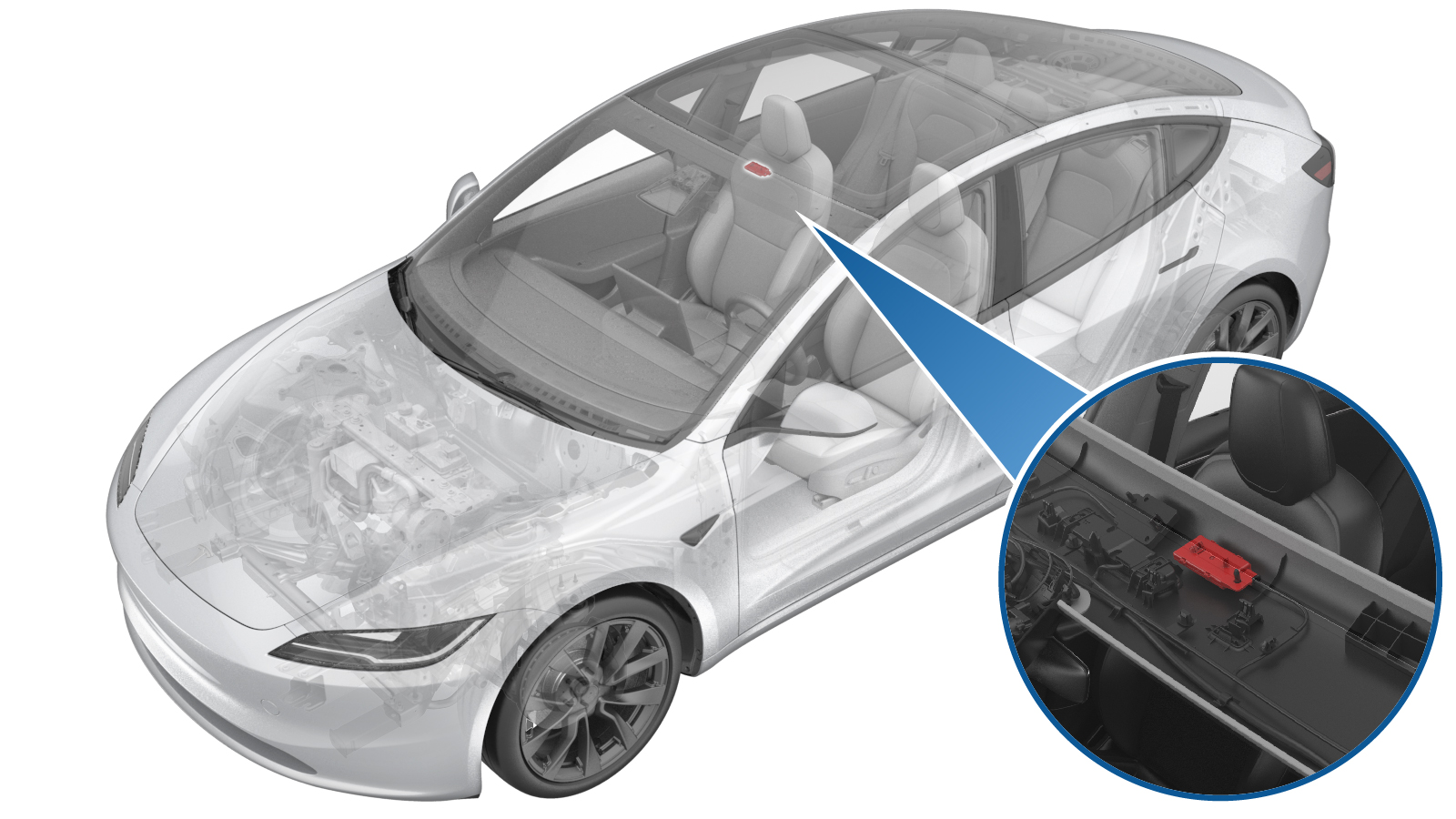
Pull the red locking tab to disengage the lock, and then hold and pull it
again to release the connector.
-
Remove the bolt that attaches the BLE
module to the vehicle, and then release the clip and remove the BLE module.
TIpUse of the following tool(s) is recommended:
- 10 mm socket
Install
-
Seat the BLE module at the proper
position, secure the clip, and then secure the bolt that attaches the BLE module to the
vehicle.10 Nm (7.4 lbs-ft)TIpUse of the following tool(s) is recommended:
- 10 mm socket
-
Engage the red locking tab to connect the connector.
-
Align the locating pin of
the front of the headliner to the slot, and then install the clips (x6) that
attach the front of the headliner to vehicle.
NoteMake sure that the door seal correctly overlaps the LH upper B-pillar trim.
- Install the rear view mirror. See Mirror - Rear View (Remove and Replace).
- Install the lower camera cover. See Camera Cover - Lower (Remove and Replace).
-
Install the LH sun visor.
See Sun Visor Assembly, LH (Remove and Replace).
WarningThe video(s) included in this procedure are meant as an overview for supplemental purposes only. Follow all of the steps listed in the procedure to avoid damage to components and/or personal injury.
- Install the LH upper A-pillar trim. See Trim - A-Pillar - Upper - LH (Remove and Replace).
- Repeat step 7 and step 6 for the RH side of the vehicle.
- Connect the LV battery power. See LV Power (Disconnect and Connect).
- Move both front seats forward.
- Install the LH upper B-pillar trim. See Trim - B-Pillar - Upper - LH (Remove and Replace).
- Install the LH middle B-pillar trim. See Trim - B-Pillar - Middle - LH (Remove and Replace).
- Install the LH lower B-pillar trim. See Trim - B-Pillar - Lower - LH (Remove and Replace).
- Install the LH lower A-pillar trim. See Trim - A-Pillar - Lower - LH (Remove and Replace).
- Install the LH instrument panel end cap. See End Cap - Instrument Panel - LH (Remove and Replace).
- Repeat step 11 through step 15 for the RH side of the vehicle.
- Install the 2nd row lower seat cushion. See Seat Cushion - 2nd Row (Remove and Replace).
- Install the 2nd row LH and RH seat side bolsters. See Bolster - Side - Seat - 2nd Row - LH (Remove and Replace).
- Move both front seats back to the original position.
- Locally connect a laptop with Toolbox to the vehicle. See Toolbox (Connect and Disconnect).
-
On the laptop, select the
Actions/Autodiag tab and search for "Service_Redeploy".
Select UPDATE_CAN-REDEPLOYvia Service Mode Plus:
- Drive Inverter Replacement ➜ Drive Inverter DIRE1L Replacement ➜ CAN Redeploy
- Drive Inverter Replacement ➜ Drive Inverter DIRE1R Replacement ➜ CAN Redeploy
- Drive Inverter Replacement ➜ Drive Inverter DIRE2 Replacement ➜ CAN Redeploy
- Drive Inverter ➜ Front Drive Inverter Replacement ➜ CAN Redeploy
- Drive Inverter ➜ Rear Drive Inverter Replacement ➜ CAN Redeploy
- Drive Inverter ➜ Rear Left Drive Inverter Replacement ➜ CAN Redeploy
- Drive Inverter ➜ Rear Right Drive Inverter Replacement ➜ CAN Redeploy
- Drive Unit ➜ Front Drive Unit Replacement ➜ CAN Redeploy
- Drive Unit ➜ Rear Drive Unit Replacement ➜ CAN Redeploy
- Thermal ➜ HVAC ➜ CAN Redeploy
- chassis ➜ DPB Post Replacement ➜ CAN Redeploy
- chassis ➜ ESP Post Replacement ➜ CAN Redeploy
- chassis ➜ IDB Post Replacement ➜ CAN Redeploy
- chassis ➜ RCU Post Replacement ➜ CAN Redeploy
- chassis ➜ ESP Replacement Panel ➜ CAN Redeploy
- chassis ➜ IBST Replacement Panel ➜ CAN Redeploy
-
On the touchscreen, verify that the release notes are present.
NoteAn error message will display on the touchscreen if the redeploy fails.
- Disable Service Mode. See Service Mode.
-
Place NFC Key cards (x2) on the top of the wireless charger pad.
WarningStacking a mobile phone and a NFC card in wireless charger may damage the card.
- On the laptop, select the Actions tab and search for "Pair NFC". Select PROC_VCSEC_C_PAIR-NFC-CARD-V2via Service Mode:Low Voltage ➜ Keys ➜ Pair Keyvia Toolbox:(link), click Run, add the number of cards to pair and click submit, and then allow the routine to complete.
-
Make sure that the following functions of the programmed NFC keys work
properly:
- Using the NFC key to tap the driver side exterior B-pillar area locks/unlocks the vehicle.
- Using the NFC key to tap the center console area behind the cup holders starts the vehicle.
- Disconnect the laptop with Toolbox from the vehicle. See Toolbox (Connect and Disconnect).
- Raise all windows and close all doors.