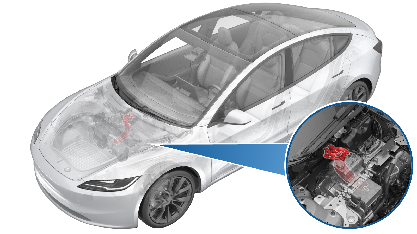
Assembly - A/C Line - Supermanifold to HVAC (Remove and Replace)
 Correction code
1820010012
FRT
0.48
NOTE: Unless
otherwise explicitly stated in the procedure, the above correction code and
FRT reflect all of the work required to perform this procedure, including
the linked procedures. Do
not stack correction codes unless explicitly told to do so.
NOTE: See Flat Rate
Times to learn more about FRTs and how
they are created. To provide feedback on FRT values, email ServiceManualFeedback@tesla.com.
NOTE: See Personal Protection
to make sure wearing proper PPE when performing the below procedure.
NOTE: See Ergonomic Precautions for safe and
healthy working practices.
- 2025-10-20: Updated the routine per the latest validation.
- 2024-01-30: Added the routines and torque specification table.
Torque Specifications
| Description | Torque Value | Recommended Tools | Reuse/Replace | Notes |
|---|---|---|---|---|
| Bolts (x2) that attach the supermanifold to HVAC A/C line to the HVAC assembly |
 28 Nm (20.6 lbs-ft) |
|
Reuse | |
| Nut that attaches the supermanifold to HVAC A/C line to the supermanifold |
 36 Nm (26.5 lbs-ft) |
|
Reuse |
Remove
- Set up the A/C machine.
- Remove the rear underhood apron. See Underhood Apron - Rear (Remove and Replace).
- Remove the cabin intake duct. See Assembly - Fresh Air Gutter - HVAC (Remove and Replace).
- Remove the fresh air duct. See Fresh Air Intake - HVAC (Remove and Replace).
- Remove the access panel. See Cover - Hood Latch (Remove and Replace).
- Remove the underhood storage unit. See Underhood Storage Unit (Remove and Replace).
- Unlock the vehicle gateway. See Gateway Unlock.
- On the touchscreen, touch and select Run to start the "Start Thermal Fill Drain (Refrigerant Only)" routine.
- Disconnect the LV battery power. See LV Power (Disconnect and Connect).
- Recover the A/C refrigerant. See A/C Refrigerant (Recovery and Recharge) (Restore).
- Remove LV power. See LV Battery (Remove and Replace).
-
Remove the bolts (x2) that attach the
supermanifold to HVAC A/C line to the HVAC assembly.
TIpUse of the following tool(s) is recommended:
- 13 mm socket
- 6 in extension
- Flex head ratchet/flex head torque wrench
WarningThe video(s) included in this procedure are meant as an overview for supplemental purposes only. Follow all of the steps listed in the procedure to avoid damage to components and/or personal injury. -
Remove the nut that attaches the
supermanifold to HVAC A/C line to the supermanifold.
TIpUse of the following tool(s) is recommended:
- 13 mm socket
- 6 in extension
- Flex head ratchet/flex head torque wrench
-
Release the supermanifold to HVAC A/C
line from the supermanifold, and then move the A/C line rearwards and up to remove
it.
Install
-
Position the supermanifold to HVAC A/C
line on the supermanifold, inserting the A/C line stud into the stud hole on the
supermanifold.
NoteLubricate the seal washers with ND-11 oil.TIpLook through the supermanifold stud hole to help locate the A/C line stud.WarningThe video(s) included in this procedure are meant as an overview for supplemental purposes only. Follow all of the steps listed in the procedure to avoid damage to components and/or personal injury.
-
Install the nut that attaches the
supermanifold to HVAC A/C line to the supermanifold.
 36 Nm (26.5 lbs-ft)TIpUse of the following tool(s) is recommended:
- 13 mm socket
- 6 in extension
- Flex head ratchet/flex head torque wrench
-
Install the bolts (x2) that attach the
supermanifold to HVAC A/C line to the HVAC assembly.
 28 Nm (20.6 lbs-ft)TIpUse of the following tool(s) is recommended:
- 13 mm socket
- 6 in extension
- Flex head ratchet/flex head torque wrench
- Install LV power. See LV Battery (Remove and Replace).
- Perform the vacuum leak test and oil injection procedure. See Vacuum Leak Test and Oil Injection.
- Recharge the A/C refrigerant. See Recharge.
- Connect LV power. See LV Power (Disconnect and Connect).
- Unlock the vehicle gateway. See Gateway Unlock.
- On the touchscreen, tap the Service Mode "wrench" (at the bottom of the touchscreen UI), and then tap , click Run, and allow the routine to complete.
- Exit Service Mode through UI. See Service Mode.
- Install the underhood storage unit. See Underhood Storage Unit (Remove and Replace).
- Install the access panel. See Cover - Hood Latch (Remove and Replace).
- Install the fresh air duct. See Fresh Air Intake - HVAC (Remove and Replace).
- Install the cabin intake duct. See Assembly - Fresh Air Gutter - HVAC (Remove and Replace).
- Install the rear underhood apron. See Underhood Apron - Rear (Remove and Replace).