2026-07-22
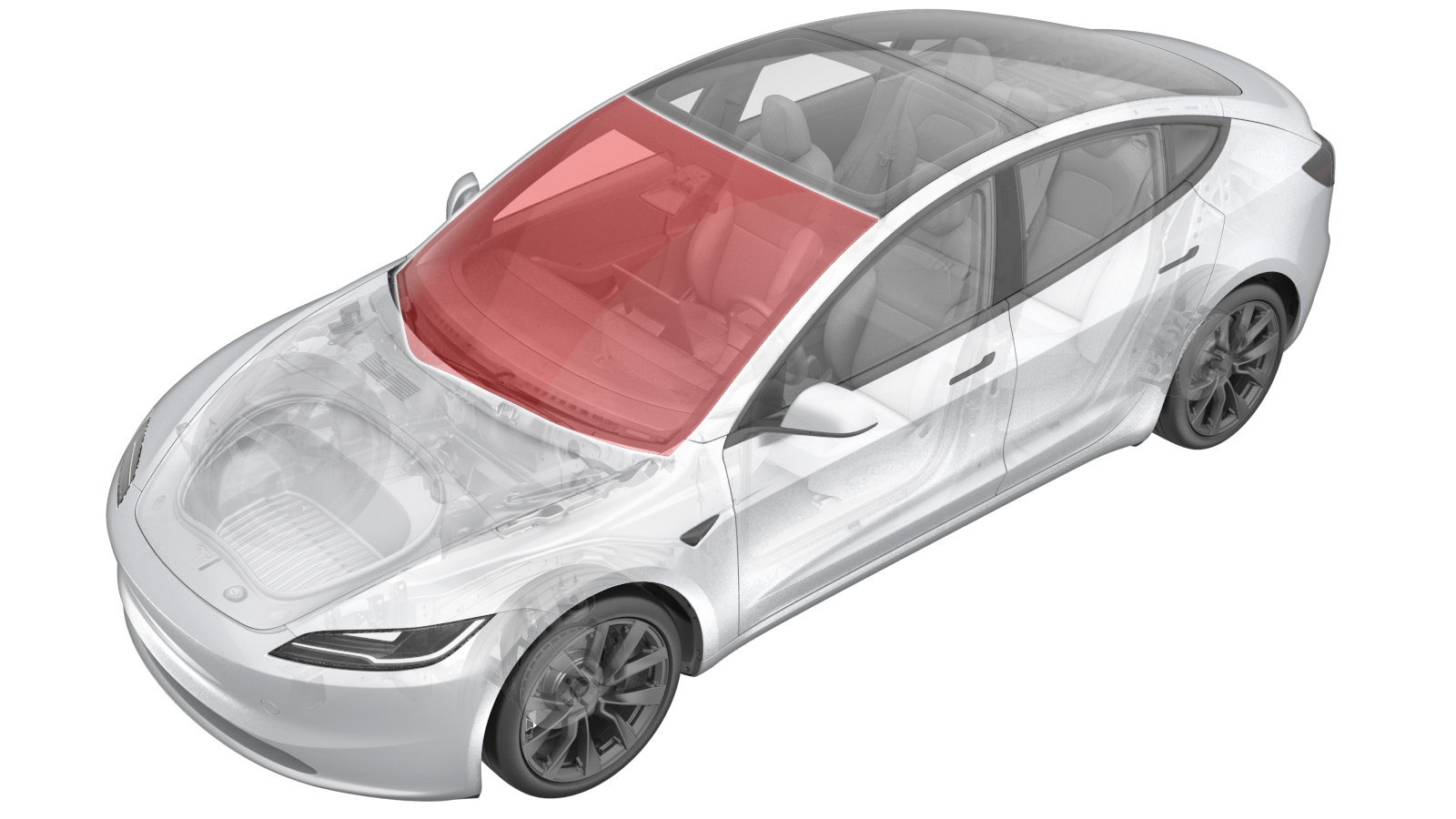
Windshield (LHD) (Remove and Replace)
 Correction code
1020030112
FRT
2.10
NOTE: Unless otherwise explicitly stated in the procedure, the correction code and FRT listed above reflect all of the work required to perform this procedure, including the linked procedures. Do not stack correction codes unless explicitly told to do so.
NOTE: See Flat Rate Times to learn more about FRTs and how they are created.
NOTE: See Personal Protection to make sure you
are wearing proper PPE when performing the procedure below.
NOTE: See Ergonomic Precautions for safe and healthy working practices.
Correction code
1020030112
FRT
2.10
NOTE: Unless otherwise explicitly stated in the procedure, the correction code and FRT listed above reflect all of the work required to perform this procedure, including the linked procedures. Do not stack correction codes unless explicitly told to do so.
NOTE: See Flat Rate Times to learn more about FRTs and how they are created.
NOTE: See Personal Protection to make sure you
are wearing proper PPE when performing the procedure below.
NOTE: See Ergonomic Precautions for safe and healthy working practices.
- 2026-07-22: Added step to change windshield configuration.
- 2026-06-10: Added warnings to set drill clutch to 1 when using a drill with the Spider tool.
- 2025-05-13: Added part numbers to equipment.
- 2025-03-26: Added note and caution to make sure vehicle is parked on a flat place.
- 2024-12-10: Added new caution about Pre-Installation Glass Inspection service requirements.
- 2024-01-18: Added the step of reinstalling the firmware at the end of the installation procedure.
CAUTION
New glass components
(windshield, roof, door, and fixed glass) must be inspected before installation to meet
Tesla’s internal standards of quality. Perform the inspection described in Pre-Installation Glass Inspection before beginning this
procedure.
Note
Make sure the vehicle is parked on a flat place.
Equipment:
- 1571168-00-A WRD Spider 3 Glass Removal Kit
- 1126456-00-A Battery Powered Drill
- 1588904-00-A Gap and Flush Tool
- 1080593-00-A Caulk and Adhesive Gun
Remove
- Remove the rear underhood apron. See Underhood Apron - Rear (Remove and Replace).
- Remove the cabin intake duct. See Assembly - Fresh Air Gutter - HVAC (Remove and Replace).
- Remove the access panel. See Cover - Hood Latch (Remove and Replace).
- Remove the underhood storage unit. See Underhood Storage Unit (Remove and Replace).
- Remove the LH and RH wiper arms and blades. See Wiper Arm - Driver Side (Remove and Replace).
- Remove the LH and RH hood hinge covers. See Cover - Hood Hinge - LH (Remove and Replace).
- Remove the LH and RH shock tower covers. See Cover - Shock Tower - LH (Remove and Install).
- Remove the cowl screen panel. See Panel - Cowl Screen (Remove and Replace).
- Remove the LH and RH instrument panel end caps. See End Cap - Instrument Panel - LH (Remove and Replace).
- Remove the LH and RH upper A-pillar trims. See Trim - A-Pillar - Upper - LH (Remove and Replace).
- Remove the LH and RH sun visors. See Sun Visor Assembly, LH (Remove and Replace).
- Remove the lower camera cover. See Camera Cover - Lower (Remove and Replace).
- Remove the rear view mirror. See Mirror - Rear View (Remove and Replace).
-
Remove the upper camera cover. See Camera Cover - Upper (Remove and Replace).
NoteNo need to remove the interior camera from the upper camera cover.
- Remove the rear view mirror glare shield. See Glare Shield - Front Camera (Remove and Replace).
- Remove the forward facing camera fan. See Fan - Triple Cam (Remove and Replace).
-
Disconnect the humidity and temperature sensor electrical connector.
- Remove the Bi-forward facing camera. See Camera - Forward Facing (Remove and Replace).
-
Release the clips (x4) and locator pin that attach the front of the headliner to the body, and then separate the front part of the headliner from the body.
CAUTIONTake care not to bend the headliner.
-
Release the clips (x6) that attach the windshield harness to the windshield fastener track bracket.
-
Remove the fastener track.
-
Release the clips (x6) that the windshield harness to the A-pillar.
- Remove the instrument panel speaker grille. See Speaker Grille - Instrument Panel (Remove and Replace).
- Place towels on the instrument panel to protect the surface.
- Apply masking tape to the exterior of both A-pillars.
-
Prepare the WRD Spider 3 glass removal kit.
TIpUse of the following tool(s) is recommended:
- 1571168-00-A WRD Spider 3 Glass Removal Kit
-
Secure the wire to the starter tool and push the tool through the urethane at the RH lower side of the windshield assembly.
CAUTIONUse the guard to prevent damage to the dash pad while using the starter tool.CAUTIONEnsure the vehicle is parked on a flat surface for the entirety of the curing process.
-
Release the line from the starter tool and wrap the line around the exterior of the windshield.
NotePull the line away from the starter tool. Make sure enough length is pulled through.NoteVerify the line sits underneath the glass.
-
Attach the anchor point to the exterior of the windshield near the starting point of the handle tool, and then secure the line to the anchor.
-
Secure the interior side of the line to the Spider cutting tool.
NoteFollow the instructions on the Spider tool. Feed the line through the opening of the cutting tool and tie a knot to secure the line in place. If the spindle is not turned the proper direction, the cutting tool will be damaged.
-
Secure the Spider cutting tool to the interior side of the windshield.
NoteNote the orientation of the cutting line. Make sure the line wraps over the large pulley and holds a 90 degree angle.
-
Install an angle driver to an electric drill and set the drill clutch to 1.
WarningFailure to set the drill clutch to 1 may result in serious injury.
-
Use the drill to turn the spindle on the cutting tool. Begin cutting urethane around
the glass.
WarningDo not begin cutting the windshield without first setting the drill clutch to 1. Failure to do so may result in serious injury.WarningWear appropriate eye and hand protection while cutting the glass assembly.CAUTIONPlace a plastic guard to protect the VIN plate when cutting in that area.TIpMove the cutting tool as needed while keeping the line close to a 90° angle.
Figure 1. Plastic guard to protect the VIN plate - Attach suction cups to the LH and RH sides of the windshield assembly.
-
With an assistant, remove the windshield assembly from the vehicle.
- Remove the suction cups from the windshield assembly.
-
Use a razor blade to remove the old urethane from the windshield flange on the vehicle.
WarningWear cut-resistant gloves and safety glasses when performing this step to avoid personal injury.
- Remove the tape from the exterior of both A-pillars.
Install
CAUTION
Use soft
materials to protect the windshield and to prevent scratching. Verify that the rubber strip
completely separates the windshield from the metal components of the body.
- Clean the windshield as needed. Take special caution to the forward-facing camera area to ensure a clear view of the forward-facing camera. See .
- Place the new windshield on a support stand with the windshield bracket facing up.
- Attach suction cups to the LH and RH sides of the windshield assembly.
- Clean the urethane path on the vehicle with an isopropyl alcohol (IPA) wipe. Allow the surface to dry before continuing to the next step.
-
Apply urethane primer to the windshield and vehicle body along the urethane path and in areas that were damaged during removal of the windshield assembly.
CAUTIONBe careful not to damage the headliner during application.NoteAllow the primer to dry for at least 2 minute.
-
Apply urethane to the windshield following the original path.
NoteMake sure that the urethane bead has a triangular cross-section of approximate width 8 mm and height 13 mm.
-
With an assistant, install the new windshield assembly onto the vehicle, but do not set it yet.
CAUTIONBe careful not to damage the headliner during installation.
- Check the gap and flush of the windshield assembly to the body before fully seating the windshield assembly.
- Fully seat the windshield assembly, check the gap and flush, and adjust if necessary.
- Remove the suction cups from the windshield assembly.
- Apply masking tape to attach the windshield assembly to the body while the urethane cures.
-
Fasten the clips (x6) that the windshield harness to the A-pillar.
- Remove the towels on the instrument panel.
- Install the instrument panel speaker grille. See Speaker Grille - Instrument Panel (Remove and Replace).
-
Fasten the clips (x6) that attach the windshield harness to the windshield fastener track bracket.
-
Fasten the clips (x4) and locator pin that attach the front of the headliner to the body.
CAUTIONTake care not to bend the headliner.
- Install the LH and RH sun visors. See Sun Visor Assembly, LH (Remove and Replace).
- Install the LH and RH upper A-pillar trims. See Trim - A-Pillar - Upper - LH (Remove and Replace).
- Install the LH and RH instrument panel end caps. See End Cap - Instrument Panel - LH (Remove and Replace).
-
Connect the humidity and temperature sensor electrical connector.
- Install the forward facing camera fan. See Fan - Triple Cam (Remove and Replace).
- Install the Bi-forward facing camera. See Camera - Forward Facing (Remove and Replace).
- Install the rear view mirror glare shield. See Glare Shield - Front Camera (Remove and Replace).
-
Install the upper camera cover. See Camera Cover - Upper (Remove and Replace).
NoteNo need to remove the interior camera from the upper camera cover.
- Install the cowl screen panel. See Panel - Cowl Screen (Remove and Replace).
- Install the LH and RH shock tower covers. See Cover - Shock Tower - LH (Remove and Install).
- Install the LH and RH hood hinge covers. See Cover - Hood Hinge - LH (Remove and Replace).
- Install the LH and RH wiper arms and blades. See Wiper Arm - Driver Side (Remove and Replace).
- Install the underhood storage unit. See Underhood Storage Unit (Remove and Replace).
- Install the access panel. See Cover - Hood Latch (Remove and Replace).
- Install the cabin intake duct. See Assembly - Fresh Air Gutter - HVAC (Remove and Replace).
- Install the rear underhood apron. See Underhood Apron - Rear (Remove and Replace).
-
Reset the Driver Assistance System (DAS).
- Perform the forward facing camera pitch verification. See Camera - Forward Facing (Pitch Verification) (Test/Adjust).
- Install the rear view mirror. See Mirror - Rear View (Remove and Replace).
- Install the lower camera cover. See Camera Cover - Lower (Remove and Replace).
- Reinstall the vehicle firmware. See Software Reinstall - Touchscreen.
- On the vehicle touchscreen, select . Select the part number of the windshield that was just installed from the dropdown menu, then select Run.
- Disable Service Mode. See Service Mode.
- Move the front seats to original position.
- Raise both front windows and close both front doors.
-
Remove the masking tape after the urethane has cured.
CAUTIONDo not drive the vehicle until the adhesive manufacturer’s recommended minimum drive-away time has passed. Dow Betaseal Express has a drive-away time of 1 hour minimum in temperatures of 0˚F (-18˚C) or warmer. If necessary, leave the tape applying pressure to the glass on the vehicle and advise the customer that they can remove it after 24 hours. Additionally, advise the customer that they should avoid high driving speeds and speed bumps for the next 24 hours.