2026-06-02
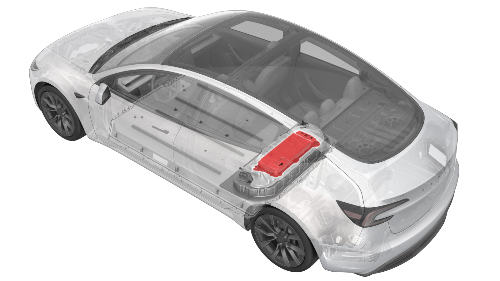
Power Conversion System (Remove and Replace)
 Correction code
1630010252
FRT
2.28
NOTE: Unless otherwise explicitly stated in the procedure, the correction code and FRT listed above reflect all of the work required to perform this procedure, including the linked procedures. Do not stack correction codes unless explicitly told to do so.
NOTE: See Flat Rate Times to learn more about FRTs and how they are created.
NOTE: See Personal Protection to make sure you
are wearing proper PPE when performing the procedure below.
NOTE: See Ergonomic Precautions for safe and healthy working practices.
Correction code
1630010252
FRT
2.28
NOTE: Unless otherwise explicitly stated in the procedure, the correction code and FRT listed above reflect all of the work required to perform this procedure, including the linked procedures. Do not stack correction codes unless explicitly told to do so.
NOTE: See Flat Rate Times to learn more about FRTs and how they are created.
NOTE: See Personal Protection to make sure you
are wearing proper PPE when performing the procedure below.
NOTE: See Ergonomic Precautions for safe and healthy working practices.
- 2026-06-02: Updated steps for LV battery disconnect/connect and attaching an LV maintainer.
- 2025-07-02: Clarified steps to drain the ancillary bay.
- 2025-04-22: Added a note to clarify previous 6 PCS fixed bolts must be upgraded to 5 bolts with part number 1115833-00-B.
Torque Specifications
| Description | Torque Value | Recommended Tools | Reuse/Replace | Notes |
|---|---|---|---|---|
| Bolts (x5) securing PCS to HV battery |
 18 Nm (13.3 lbs-ft) |
|
Reuse | Ensure only the 8mm fasteners are removed, Do not remove the T30 fasteners. |
Remove
- Raise and support vehicle.
- Open all four doors and lower all four windows.
- Move LH front seat forward.
- Enter Service Mode. See Service Mode.
- Select , click Runto let routine complete.
- Perform the Vehicle HV Disablement Procedure. See Vehicle HV Disablement Procedure (Test/Adjust).
- Remove the rear skid plate. See Skid Plate - HV Battery - Rear (Remove and Replace).
- Vacuum drain the coolant from the ancillary bay. See Ancillary Bay Coolant (Drain and Refill) (Test/Adjust).
- Remove the pyrotechnic battery disconnect. See Pyro Disconnect - HV Battery (Remove and Replace).
-
Install the pyrotechnic disconnect
dummy.
-
Use a bungee cord to secure HVC in an
upwards position.
NoteWrap bungee around RH headrest.
-
Position absorbent sheets below and
around PCS coolant inlet hose to avoid excess coolant dripping.
-
Disconnect the PCS coolant inlet hose
from the PCS.
-
Position absorbent sheets below and
around the PCS coolant outlet hose to avoid excess coolant dripping.
-
Disconnect the PCS coolant outlet hose
from the PCS and install plugs.
-
Disconnect the PCS logic connector
from the PCS.
-
Disconnect the PCS LV connector from
the PCS.
NoteRelease the locking tab by pulling upward, may need plastic trim tool to help lift the connector upward.
-
Disconnect the PCS to DC bus HV
connector.
NoteRelease the locking tab by pulling upward, may need plastic trim tool to help lift the connector upward.
-
Disconnect the PCS to fastcharge
contactor HV harness connector.
NoteRelease the locking tab by pulling upward, may need plastic trim tool to help lift the connector upward.
-
For vehicles that have a 1-Phase
charging system: release the clips (x2) that attach the PCS to fastcharge contactor HV
harness to the PCS and set the harness aside.
NoteThere are differences in different regions, depending on having a 1-Phase or 3-Phase charging system: 1-Phase has a wiring harness fixing bracket, 3-Phase comes without this bracket.
-
Remove the bolts (x5) that attach the
PCS to the HV battery.
TIpUse of the following tool(s) is recommended:
- SKT, 1/4" SQ DR, 8MM, HV INSULATED
-
Secure suction cups to the PCS.
NoteContinue pressing plunger until red line is no longer visible.
-
Lift the PCS up and out of the
ancillary bay area and remove the PCS from vehicle.
-
Remove the suction cups from the old
PCS.
Install
-
Remove the PCS plugs from the new
PCS.
-
Drain water from the new PCS.
-
Reinstall plugs on the new PCS prior
to installing it into vehicle.
-
Attach suction cups to the PCS.
NoteContinue pressing plunger until red line is no longer visible.
-
Position the PCS into the ancillary
bay.
NoteEnsure all busbar insulators beneath PCS are present, slightly tilt rear of PCS upward and lower into position, align datum into PCS holes, inspect for any coolant residue inside the ancillary bay and clean with absorbent sheets if necessary.
-
Remove the suction cups from
PCS.
-
Install the bolts securing PCS to the
HV battery.18 Nm (13.3 lbs-ft)TIpUse of the following tool(s) is recommended:
- SKT, 1/4" SQ DR, 8MM, HV INSULATED
NoteFasteners count may vary depending on production date, Follow torque specification for number of fasteners equipped.NoteIf the PCS came with 6 bolts then install new bolt and change it to 5 bolts (1115833-00-B). -
For vehicles that have a 1-Phase charging system: release the clips (x2) that attach
the PCS to fastcharge contactor HV harness to the PCS and set the harness aside.
NoteThere are differences in different regions, depending on having a 1-Phase or 3-Phase charging system: 1-Phase has a wiring harness fixing bracket, 3-Phase comes without this bracket.
-
Connect the PCS to fastcharge
contactor HV harness connector.
NotePush connector downward then push the locking tab downward to install connector, make sure the connector is fully seated.
-
Connect the PCS to DC bus HV
connector.
NotePush connector downward then push the locking tab downward to install connector, make sure the connector is fully seated.
-
Connect the PCS LV connector to the
PCS.
NotePush connector downward then push the locking tab downward to install connector, make sure the connector is fully seated.
-
Connect the PCS logic connector to the
PCS.
-
Remove the plug from the PCS inlet
hose.
-
Replace the o-rings on the PCS inlet
hose.
-
Secure the inlet hose to the
PCS.
NotePlace absorbent sheet under hose to catch excess coolant, caution when installing this hose, it's difficult to align hose to coupling, use caution not to damage the o-rings, perform push-pull-push test to make sure coolant hose is fully latched, then visually verify clip is fully seated.
-
Remove the plug from the PCS outlet
hose.
-
Replace the o-rings on the PCS outlet
hose.
-
Secure the PCS outlet hose to the
PCS.
NotePlace absorbent sheet under hose to catch excess coolant, caution not to damage the o-rings, perform push-pull-push test to make sure coolant hose is fully latched, then visually verify clip is fully seated, visually inspect area for any coolant residue, clean with shop towel if necessary
-
Move the HVC back to its original
position.
NoteRelease bungee from back of headrest.
- Perform the ancillary bay coolant leak test. See Ancillary Bay Coolant Leak Test (Inspection).
- Install the rear skid plate. See Skid Plate - HV Battery - Rear (Remove and Replace).
- Install the pyrotechnic battery disconnect. See Pyro Disconnect - HV Battery (Remove and Replace).
-
Install the ancillary bay cover. See
Ancillary Bay Cover (Remove and Replace).
NoteBefore installing the ancillary bay cover, inspect the ancillary bay cover seal and confirm there is no visual damage. If the seal is torn and/or delaminated, replace the ancillary bay cover.
- Perform ancillary bay coolant refill. See Ancillary Bay Coolant (Drain and Refill) (Test/Adjust).
- Connect LV power. See LV Power (Disconnect and Connect).
- Connect the low-voltage battery maintainer. See LV Maintainer (Connect and Disconnect) (Maintenance).
- Select , click Runto let routine complete.
- Reinstall software. See Software Reinstall - Touchscreen.
- Disconnect low-voltage battery maintenance charger. See LV Maintainer (Connect and Disconnect) (Maintenance).
- Select , click Runto let routine complete.
-
Inspect coolant level and top off as necessary.
NoteEnsure that fluid level is at Max line.
- Select , clickRunto let routine complete.
- Select , clickRunto let routine complete.
- Install the 2nd row seat cushion. See Seat Cushion - 2nd Row (Remove and Replace).
- Install the rear underhood apron. See Underhood Apron - Rear (Remove and Replace).