2026-02-10
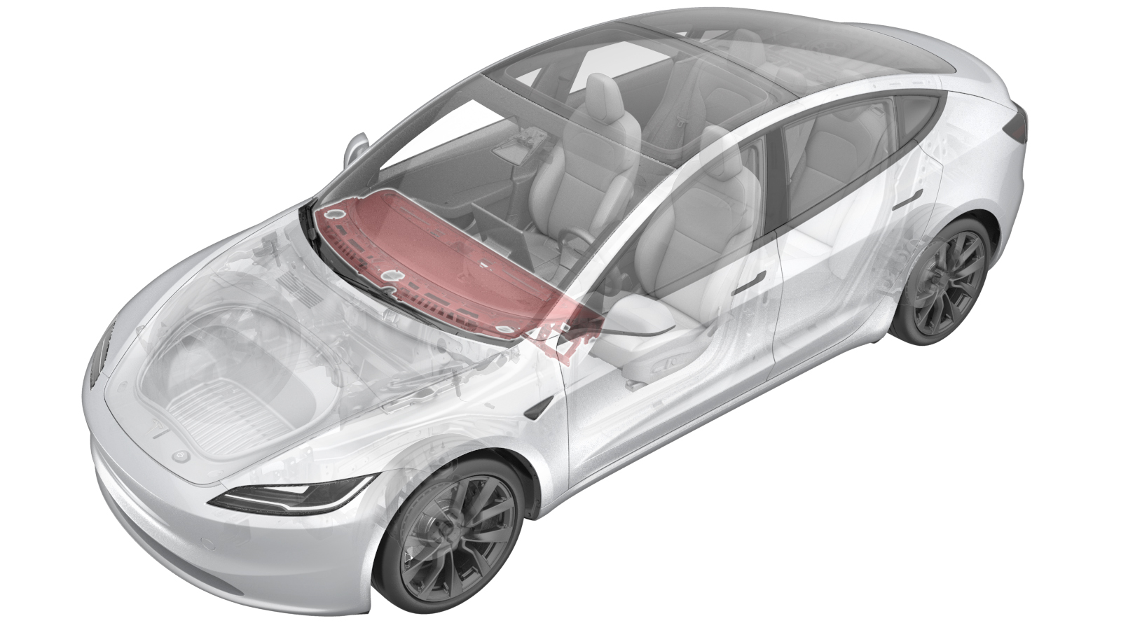
IP Carrier (Remove and Replace)
 Correction code
1405010012
1.74
NOTE: Unless otherwise explicitly stated in the procedure, the correction code and FRT listed above reflect all of the work required to perform this procedure, including the linked procedures. Do not stack correction codes unless explicitly told to do so.
NOTE: See Flat Rate Times to learn more about FRTs and how they are created.
NOTE: See Personal Protection to make sure you
are wearing proper PPE when performing the procedure below.
NOTE: See Ergonomic Precautions for safe and healthy working practices.
Correction code
1405010012
1.74
NOTE: Unless otherwise explicitly stated in the procedure, the correction code and FRT listed above reflect all of the work required to perform this procedure, including the linked procedures. Do not stack correction codes unless explicitly told to do so.
NOTE: See Flat Rate Times to learn more about FRTs and how they are created.
NOTE: See Personal Protection to make sure you
are wearing proper PPE when performing the procedure below.
NOTE: See Ergonomic Precautions for safe and healthy working practices.
- 2026-02-10: Updated the screw torque values securing the vent and duct to the IP carrier.
- 2025-02-14: Updated procedure to most recent validation.
Remove
-
Remove the IP carrier from the
vehicle. See IP Carrier (Remove and Install).
WarningThe video(s) included in this procedure are meant as an overview for supplemental purposes only. Follow all of the steps listed in the procedure to avoid damage to components and/or personal injury.
- Put the old IP carrier on a stand.
-
Remove the screws (x2) that attach the
LH defrost duct to the IP carrier.
-
Remove the LH defrost duct from the IP
carrier.
-
Disconnect the LH air duct height
adjustment actuator connector.
-
Disconnect the LH air duct horizontal
adjustment actuator connector.
-
Disconnect the ETC connector.
-
Remove the LH IP harness from the IP
carrier.
Note4x clips
-
Remove the screws (x5) that attach the
LH air vent to the IP carrier.
Note5x screws, 4x datums
-
Remove the LH air vent from the IP
carrier.
-
Remove the screws (x2) that attach the
RH defrost duct to the IP carrier.
-
Remove the RH defrost duct from the IP
carrier.
-
Disconnect the RH passenger air duct
height adjustment actuator connector.
-
Disconnect the RH passenger air duct
horizontal adjustment actuator connector.
-
Remove the RH IP harness from the IP
carrier.
Note2x clips, 2x slots
-
Remove the screws that attach the RH
passenger air vent to the IP carrier.
Note5x screws, 4x datums
-
Remove the passenger air vent from the
IP carrier.
-
Remove and discard the bolts (x6) that
attach the passenger air bag to the IP carrier.
Install
-
Put the new IP carrier on a
stand.
NoteRecommend assistance
-
Install new bolts (x6) that attach the
passenger air bag to the new IP carrier (torque 8 Nm).
Note6x patch bolts 1116594-00-B.
-
Install the passenger air vent to the
IP carrier.
-
Install the screws (x5) that attach
the passenger air vent to the IP carrier (torque 0.9 Nm).
Note5x screws, 3x datums.
-
Install the clips (x2) and slots (x2)
that attach the RH IP harness to the IP carrier.
-
Connect the passenger air duct
horizontal adjustment actuator connector.
-
Connect the passenger air duct height
adjustment actuator connector.
- Install the RH defrost duct to the IP carrier.
-
Install the screws (x2) that attach
the RH defrost duct to the IP carrier (torque 0.9 Nm).
-
Install the driver air vent to the IP
carrier.
-
Install the screws (x5) that attach
the driver air vent to the IP carrier (torque 0.9 Nm).
Note5x screws, 4x datums.
-
Install the clips (x4) that attach the
LH IP harness to the IP carrier.
-
Connect the ETC connector.
-
Connect the LH air duct horizontal
adjustment actuator connector.
-
Connect the LH air duct height
adjustment actuator connector.
-
Install the LH defrost duct to the IP
carrier.
-
Install the screws (x2) that attach
the LH defrost duct to the IP carrier (torque 0.9 Nm).
-
Install the IP carrier onto the cross
car beam.
NoteBe careful not to press the speaker connector and ambient light connector onto the IP.WarningThe video(s) included in this procedure are meant as an overview for supplemental purposes only. Follow all of the steps listed in the procedure to avoid damage to components and/or personal injury.
- Perform all further installation steps outlined in IP Carrier (Remove and Install).