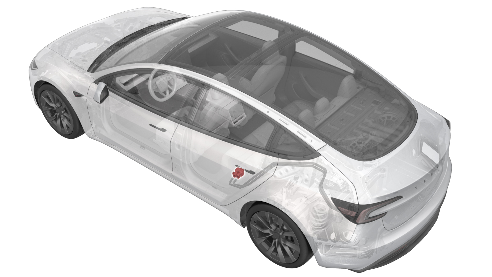
Connector - Battery Side - Charge Port to HV Battery Busbar (Remove and Replace)
 Correction code
4450010062
FRT
1.02
NOTE: Unless otherwise explicitly stated in the procedure, the correction code and FRT listed above reflect all of the work required to perform this procedure, including the linked procedures. Do not stack correction codes unless explicitly told to do so.
NOTE: See Flat Rate Times to learn more about FRTs and how they are created.
NOTE: See Personal Protection to make sure you
are wearing proper PPE when performing the procedure below.
NOTE: See Ergonomic Precautions for safe and healthy working practices.
Correction code
4450010062
FRT
1.02
NOTE: Unless otherwise explicitly stated in the procedure, the correction code and FRT listed above reflect all of the work required to perform this procedure, including the linked procedures. Do not stack correction codes unless explicitly told to do so.
NOTE: See Flat Rate Times to learn more about FRTs and how they are created.
NOTE: See Personal Protection to make sure you
are wearing proper PPE when performing the procedure below.
NOTE: See Ergonomic Precautions for safe and healthy working practices.
Equipment:
- 1076921-00-A Insulation Multimeter, Fluke 1587
- 1130480-02-A Slim Test Probes
- 1617321-00-A Busbar HV Connector Clamp
- 1076927-00-A Hioki RM 3548
- 1076928-00-A Test Probes - Hioki 9461
Only
technicians who have completed all required certification courses are permitted to
perform this procedure. Tesla recommends third party service provider technicians
undergo equivalent training before performing this procedure. For more information on
Tesla Technician requirements, or descriptions of the subject matter for third parties,
see HV Certification Requirements. Proper personal protective equipment (PPE) and insulating HV
gloves with a minimum rating of class 0 (1000V) must
be worn at all times a high voltage cable, busbar, or fitting is handled. Refer to Tech Note TN-15-92-003, High Voltage Awareness
Care Points
for additional safety
information.
Remove all jewelry (watches, bracelets, rings, necklaces, earrings, ID tags, piercings, etc.) from your person, and all objects (keys, coins, pens, pencils, tools, fasteners, etc.) from your pockets before performing any procedure that exposes you to high voltage.
Proper Personal Protective Equipment (PPE) is required to perform this procedure:
- High Voltage (HV) insulating gloves
- Leather glove protectors
- High voltage glove tester
- Safety glasses
- Electrical hazard rated safety shoes
A glove inflator is the only recommended way to test HV gloves. Both HV gloves must pass testing before beginning this procedure. If either glove does not pass the air check, discard the pair.
- North America: HV gloves can be used up to 12 months after the testing date printed on the glove, but only 6 months after first use even if the gloves are still within the 12 month period. If the gloves were not put into service during the 12-month period following the testing date, they must be retested before being put into service.
- Europe: Class 0 (1000V) HV gloves have no expiration date and may be used if they pass the pre-use assessment and the periodic inspection.
- Asia Pacific: Follow the
expiration date stated by the HV glove manufacturer, and:
- o China only: Test the gloves every 6 months according to GB/T 17622.
Torque Specifications
| Description | Torque Value | Recommended Tools | Reuse/Replace | Notes |
|---|---|---|---|---|
| Screws (x2) that attach the HV busbar leads to the HV connector |
 4 Nm (2.9 lbs-ft) |
|
Reuse |
Remove
- Remove the charge port to HV battery busbars. See Busbar - Charge Port to HV Battery (China) (Remove and Replace).
-
Remove the screws (x2) that
attach the HV busbar leads to the HV connector.
TIpUse of the following tool(s) is recommended:
- Torx T20 socket
- 4 in extension
- Ratchet/torque wrench
-
Release the clips (x2) that attach the HV busbar leads to the HV
connector.
WarningThe video(s) included in this procedure are meant as an overview for supplemental purposes only. Follow all of the steps listed in the procedure to avoid damage to components and/or personal injury.
-
Remove the HV busbar
connector plug from the HV Busbar assembly.
NotePull the HV connector straight away from the busbars. The busbar leads will not separate from the connector if pulled at an angle.
-
Remove the HV busbar connector sealing retainers (x2) and clips from the HV
Busbar assembly.
NoteThe new HV busbar connector includes sealing retainers and clips.
Install
-
Install the HV busbar
connector plug onto the HV busbar leads. The connector is fully seated when
the busbar lead screw holes are aligned with the connector housing screw
holes.
-
Install the screws (x2) that
attach the HV busbar leads to the HV connector.4 Nm (2.9 lbs-ft)TIpUse of the following tool(s) is recommended:
- Torx T20 socket
- 4 in extension
- Ratchet/torque wrench
- Install the charge port to HV battery busbars. See Busbar - Charge Port to HV Battery (China) (Remove and Replace).