2025-10-21
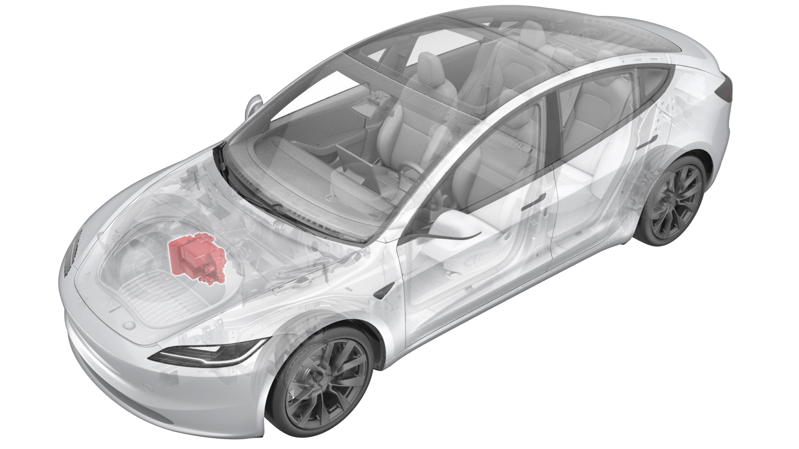
Supermanifold (Remove and Replace)
 Correction code
1840010012
FRT
2.22
NOTE: Unless otherwise explicitly stated in the procedure, the correction code and FRT listed above reflect all of the work required to perform this procedure, including the linked procedures. Do not stack correction codes unless explicitly told to do so.
NOTE: See Flat Rate Times to learn more about FRTs and how they are created.
NOTE: See Personal Protection to make sure you
are wearing proper PPE when performing the procedure below.
NOTE: See Ergonomic Precautions for safe and healthy working practices.
Correction code
1840010012
FRT
2.22
NOTE: Unless otherwise explicitly stated in the procedure, the correction code and FRT listed above reflect all of the work required to perform this procedure, including the linked procedures. Do not stack correction codes unless explicitly told to do so.
NOTE: See Flat Rate Times to learn more about FRTs and how they are created.
NOTE: See Personal Protection to make sure you
are wearing proper PPE when performing the procedure below.
NOTE: See Ergonomic Precautions for safe and healthy working practices.
- 2025-10-21: Updated A/C line torque values per the latest validation.
- 2025-08-21: Added coolantPumpType configuration step.
- 2024-04-24: Added steps of calculating the oil amount of desiccant bag and accumulator, and changed the way of removing the supermanifold from the vehicle directly to removing the supermanifold together with the shock tower brace and the compressor, and then separating the supermanifold from the assembly.
Note
This procedure requires the A/C
Refrigerant (Recovery and Recharge) procedure to be performed. If not already
automatically added to the Service Visit, add correction code 18200102 as a
separate correction within the same activity to the Service Visit.
Equipment:
- 1711245-00-A Snap On Ecotechnics Dual Gas AC Machine
- 1135762-00-A Kit, Svc Plug, Cooling Hose, Model 3
- 1600279-00-A AC Oil Flush Adapter Set, Model Y
- 1120026-00-A AC SERVICE MACHINE, ROBINAIR, 34788NI-H
- 1050448-00-B COOLANT VACUUM FILL - JTC
- 1076921-00-A Fluke 1587 multi-meter
- 1130480-02-A DMM TOOLKIT, SLIM PROBES, GENERIC
- 1065131-00-A TOOL KIT, BATT COOLANT DRN & FILL
- 1479505-00-A KIT, M3 VACUUM FILL COOLANT ADAPTER
Remove
- Connect the A/C machine to power, turn the power switch on, and select gas type.
-
Place the vehicle on the 2-post
lift.
TIpEnsure the vehicle is not charging.
- Open all doors and lower all windows.
- Recover the A/C refrigerant. See A/C Refrigerant (Recovery and Recharge) (Restore).
- While recovering, perform the vehicle HV disablement procedure. See Vehicle HV Disablement Procedure (Test/Adjust).
- While recovering, remove the fresh intake duct. See Fresh Air Intake - HVAC (Remove and Replace).
- While recovering, remove the LV battery. See LV Battery (Remove and Replace).
- Remove the A/C hoses from vehicle.
- Remove the front aero shield panel. See Panel - Aero Shield - Front (Remove and Replace).
- Remove the desiccant. See Desiccant (Remove and Replace).
- Weigh the desiccant bag. This is considered the "wet weight."
- Determine the "dry weight" of the desiccant bag: Inspect the bag for a label that contains the Part Number (P), Serial Number (S), and Dry Weight (W). If the label is missing, or if the dry weight is not visible, assume the dry weight is 90.4 grams.
- Subtract the dry weight from the wet weight. This is the amount of oil that must be added to the system in addition to the oil that was removed during refrigerant recovery. Note this amount for later.
-
Stick a steel ruler into the accumulator to measure the refrigerant oil level inside
the accumulator.
NoteLevel will vary per vehicle. Keep the steel ruler vertical during measurement, and record the measurement in millimeters.
- Multiply the measurement by 5.6 and add 15 to convert it to grams. Record the measurement in grams.
- Calculate the total oil loss from AC recovery, desiccant bag, and accumulator. Record the total oil amount. This amount will be used for oil injection at later step.
-
Remove the coolant bottle cap.
- Position a coolant drain container underneath the front of the HV battery.
-
Release the clip, disconnect the front
drive unit powertrain bypass hose from the supermanifold and plug the hose and the
supermanifold.
-
Release the spring clip, disconnect
the radiator outlet hose from the supermanifold, and then plug the hose and
supermanifold.
-
Release the spring clip, disconnect
the radiator inlet hose from the supermanifold, and then plug the hose and
supermanifold.
-
Release the spring clip, disconnect
the chiller to battery hose from the supermanifold, and then plug the hose and
supermanifold.
-
Release the spring clip, disconnect
the powertrain supply hose from the supermanifold, and then plug the hose and
supermanifold.
-
Release the clip, disconnect the HV
battery return hose from the supermanifold, and then plug the hose and
supermanifold.
-
Disconnect the thermal sub-harness
electrical connector from the front body controller module.
-
Remove the clip that attaches the
thermal sub-assembly harness to the front harness guide cover.
- Remove the supermanifold to compressor A/C line. See Assembly - A/C Line - Supermanifold to Compressor (Remove and Replace).
-
Remove the bolts (x2) that attach the
supermanifold to HVAC A/C line to the HVAC assembly.
TIpUse of the following tool(s) is recommended:
- 13 mm socket
- 6 in extension
- Cordless Ratchet/Impact Driver
-
Remove the shock tower beam together
with the supermanifold and A/C compressor. See A/C Compressor (Remove and Replace) and Brace - Shock Tower (Remove and Replace).
-
Remove the bolts (x2) that attach the
supermanifold to the shock tower beam.
NoteRotate the supermanifold counter-clockwise under the shock tower support beam.
-
Remove the nut that attaches the
supermanifold to HVAC A/C line to the supermanifold, and then remove the supermanifold
to HVAC A/C line assembly.
TIpUse of the following tool(s) is recommended:
- 13 mm socket
- 6 in extension
- Cordless Ratchet/Impact Driver
-
Take note of the old and new part
numbers and serial numbers for the supermanifold.
NoteThe label is located in front of the accumulator, document part numbers and serial numbers into the repair order.
Install
-
Position the supermanifold assembly to
the shock tower brace, and install the bolts (x2) to secure it.
 31 Nm (22.9 lbs-ft)NoteRotate the supermanifold counter-clockwise and install it under the shock tower support beam.TIpUse of the following tool(s) is recommended:
- 15 mm socket
- Flex head ratchet/flex head torque wrench
-
Replace the seal washers (x5) on the
supermanifold to HVAC A/C line on the supermanifold side.
NoteLubricate the seal washers with ND-11 oil.
-
Replace the seal washers (x5) on the
supermanifold to HVAC A/C line on the HVAC side.
NoteLubricate the seal washers with ND-11 oil.
-
Hand-tighten the nut that attaches the
supermanifold to HVAC A/C line to the supermanifold.
-
Torque the nut that attaches the
supermanifold to HVAC A/C line to the supermanifold.36 Nm (26.5 lbs-ft)TIpUse of the following tool(s) is recommended:
- 13 mm socket
- 6 in extension
- Flex head ratchet/flex head torque wrench
-
Install the shock tower beam together with the supermanifold and A/C compressor. See
A/C Compressor (Remove and Replace) and Brace - Shock Tower (Remove and Replace).
-
Install the bolts (x2) that attach the
supermanifold to HVAC A/C line to the HVAC assembly.28 Nm (20.6 lbs-ft)TIpUse of the following tool(s) is recommended:
- 13 mm socket
- 6 in extension
- Flex head ratchet/flex head torque wrench
-
Remove the plugs from the
supermanifold and radiator inlet hose, immediately connect the radiator inlet hose to
the supermanifold, and then fasten the clip.
NotePerform a push-pull-push test on the fittings to make sure that they are secure.
-
Remove the plugs from the
supermanifold and radiator outlet hose, immediately connect the radiator outlet hose to
the supermanifold, and then fasten the clip.
NotePerform a push-pull-push test on the fittings to make sure that they are secure.
-
Remove the plugs from the
supermanifold and front drive unit powertrain bypass hose, immediately connect the front
drive unit powertrain bypass hose to the supermanifold, and then fasten the clip.
NotePerform a push-pull-push test to make sure that the hose is secure.
-
Install the clip that attaches the
thermal sub-assembly harness to the front harness guide cover.
-
Connect the thermal sub-harness
electrical connector to the front body controller.
-
Remove the plugs from the
supermanifold and HV battery return hose, immediately connect the HV battery return hose
to the supermanifold, and then fasten the clip.
NotePerform a push-pull-push test to make sure that the hose is secure.
-
Remove the plugs from the
supermanifold and powertrain supply hose, immediately connect the powertrain supply hose
to the supermanifold, and then fasten the clip.
NotePerform a push-pull-push test to make sure that the hose is secure.
-
Remove the plugs from the
supermanifold and chiller to battery hose, immediately connect the chiller to battery
hose to the supermanifold, and then fasten the clip.
NotePerform a push-pull-push test to make sure that the hose is secure.
-
Connect the powertrain supply hose
sensor electrical connector.
NoteThe harness and coolant hose are color coded, match the harness color with the coolant hose color.
-
Connect the chiller to battery hose
sensor electrical connector.
NoteThe harness and coolant hose are color coded, match the harness color with the coolant hose color.
- Install the supermanifold to compressor A/C line. See Assembly - A/C Line - Supermanifold to Compressor (Remove and Replace).
- Install the LV battery. See LV Battery (Remove and Replace).
- Connect the LV power. See LV Power (Disconnect and Connect).
- Enable Service Mode Plus. See Service Mode Plus
- Unlock the vehicle gateway. See Gateway Unlock.
- Tap to inspect the current coolant pump configuration. If the configuration is not DUAL_MIX, change it to DUAL_MIX.
- On the touchscreen, touch , click Run, and allow the routine to complete.
-
Perform the vacuum leak test and
inject oil. See Vacuum Leak Test and Oil Injection.
NoteIf the procedure takes more than 5 hours, perform the procedure again.
- Recharge the A/C refrigerant. See A/C Refrigerant (Recovery and Recharge) (Restore).
- Perform a cooling system vacuum refill. See Cooling System - Vacuum Refill (Test/Adjust).
- Reinstall the software. See Software Reinstall - Touchscreen.
-
On the touchscreen, perform the
following steps:
-
Inspect the coolant level, top off as
necessary, and then install the coolant bottle cap.
NoteEnsure that the coolant level is at the "Max" line.
- On the touchscreen, touch , click Run, and allow the routine to complete.
- Touch , then click the START button next to Test Thermal Performance, click Run, and allow the routine to complete.
- Touch the START button next to Test HVAC Performance, click Run, and then allow the routine to complete.
- Exit Service Mode. See Service Mode.
- Remove the fluid catcher from underneath the vehicle.
- Install the front aero shield panel. See Panel - Aero Shield - Front (Remove and Replace).
- Install the fresh intake duct. See Fresh Air Intake - HVAC (Remove and Replace).
- Install the underhood storage unit. See Underhood Storage Unit (Remove and Replace).
- Install the 2nd row lower seat cushion. See Seat Cushion - 2nd Row (Remove and Replace).
- Raise all windows and close all doors.
- Remove the lift arms from below the vehicle.