2026-06-10
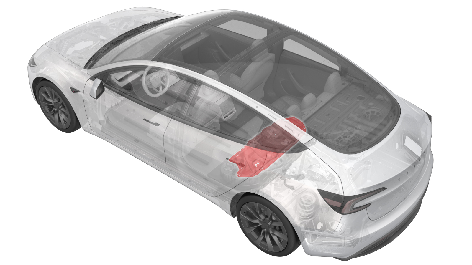
Ancillary Bay Cover (Remove and Install)
 Correction code
1630010281
0.66
NOTE: Unless otherwise explicitly stated in the procedure, the correction code and FRT listed above reflect all of the work required to perform this procedure, including the linked procedures. Do not stack correction codes unless explicitly told to do so.
NOTE: See Flat Rate Times to learn more about FRTs and how they are created.
NOTE: See Personal Protection to make sure you
are wearing proper PPE when performing the procedure below.
NOTE: See Ergonomic Precautions for safe and healthy working practices.
Correction code
1630010281
0.66
NOTE: Unless otherwise explicitly stated in the procedure, the correction code and FRT listed above reflect all of the work required to perform this procedure, including the linked procedures. Do not stack correction codes unless explicitly told to do so.
NOTE: See Flat Rate Times to learn more about FRTs and how they are created.
NOTE: See Personal Protection to make sure you
are wearing proper PPE when performing the procedure below.
NOTE: See Ergonomic Precautions for safe and healthy working practices.
- 2026-06-10: Added information for Service Cover (EMEA only)
Equipment:
- 1127845-00-A Asy, Service Cover, Penthouse, Model 3
- 1059330-00-B Skt, 1/4in Dr, 5-Lobe Torx Plus External
- 1076971-02-A Wrench, Torque + Angle, 1/4" Dr
- 1108272-00-B Cap, Logic Conn, Inv, 3DU
Warning
Remove
all jewelry (watches, bracelets, rings, necklaces, earrings, ID tags, piercings, etc.)
from your person, and all objects (keys, coins, pens, pencils, tools, fasteners, etc.)
from your pockets before performing any procedure that exposes you to high
voltage.
Warning
If
corrective eyewear is necessary to safely perform any procedure, make sure that the
eyewear is securely restrained to the head and cannot fall
off.
Warning
Only
technicians who have completed all required certification courses are permitted to
perform this procedure. Tesla recommends third party service provider technicians
undergo equivalent training before performing this procedure. For more information on
Tesla Technician requirements, or descriptions of the subject matter for third parties,
see HV Certification Requirements. Proper personal protective equipment (PPE) and insulating HV
gloves with a minimum rating of class 0 (1000V) must
be worn at all times a high voltage cable, busbar, or fitting is handled. Refer to Tech Note TN-15-92-003,
High Voltage Awareness Care Pointsfor additional safety information.
Warning
When servicing the
ancillary bay cover and components in or around the ancillary bay, there is a possibility of
encountering metal flashing on the inner edge of the vehicle single-piece rear casting.
These sharp protrusions are a cut hazard, and proper PPE should be worn if there is a chance
of contacting the flashing unprotected. If not already wearing leather over gloves, then at
least wear cut-resistant gloves when the flashing is present.
Torque Specifications
| Description | Torque Value | Recommended Tools | Reuse/Replace | Notes |
|---|---|---|---|---|
| Bolts (x3) that attach the ancillary bay cover to the high voltage controller |
 5 Nm (3.7 lbs-ft) + 30 Degrees |
|
Reuse | |
| Bolts (x18) that attach the ancillary bay cover to the HV controller |
8 Nm (5.9 lbs-ft) |
|
Reuse |
CAUTION Use
an External Torx E10 5-Lobe socket that is not magnetized. Sockets
with magnets will not fully grip and can possibly strip the bolt
head. Note Torque these
fasteners in the sequence specified in the installation step. Note These bolts are
attached to the ancillary bay cover. |
Remove
- Perform the Vehicle HV Disablement Procedure. See Vehicle HV Disablement Procedure (Test/Adjust).
-
Disconnect the electrical harness from the high voltage controller connector.
NoteThe HV battery positive contactor and negative contactor open with a clunk sound.
-
Install the logic connector cap onto the high voltage controller connector to prevent mistaken reconnection and protect the connector.
-
Remove the bolts (x3) that attach the ancillary bay cover to the high voltage controller.
WarningThe video(s) included in this procedure are meant as an overview for supplemental purposes only. Follow all of the steps listed in the procedure to avoid damage to components and/or personal injury.TIpUse of the following tool(s) is recommended:
- Torque wrench with angle measurement
- External Torx E10 5-Lobe
-
Remove the bolts (x18) that attach the ancillary bay cover to the HV battery.
TIpUse of the following tool(s) is recommended:
- External Torx E10 5-Lobe
- Put on HV insulating gloves and leather outer gloves before continuing this procedure.
-
Remove the ancillary bay cover from the vehicle.
WarningRemove the ancillary bay cover from the vehicle while standing outside the vehicle to reduce the risk of falling into the open HV battery.CAUTIONFor EMEA only: Install a Service Cover on the Ancillary Bay if required due to training requirements. E.g. for pyrotechnic disconnect replacement by technicians who are not certified for all Ancillary Bay procedures.
Install
- Use IPA wipes to clean the ancillary bay cover gasket surface, and the mating surface of the HV battery.
-
If the aluminum tape retrofit patch is
missing or damaged, remove the patch (if present), clean the area with an IPA wipe,
apply another patch of aluminum tape, and wet out the patch with a silicone roller to
set the adhesive.
TIpUse of the following tool(s) is recommended:
- 3M 425 Aluminum Foil Tape - 0601363
Figure 1. 5-Bolt to 4-Bolt Patch 50mm x 50mm Figure 2. 4-Bolt to 3-Bolt Patch 30mm x 30mm -
Inspect ancillary bay walls for damage.
NoteAny dent or depression in the seal that causes it to not be flat will result in a leak, and cannot be reused. Any paint that comes off the ancillary bay wall, whether or not it sticks to the seal, will require enclosure leak test when reassembled.
-
Inspect the ancillary bay cover seal to confirm it has no visual damage.
NoteImage up close for clarity. Delaminated and torn seals cannot be reused.
-
Install the ancillary bay cover to the
HV battery.
WarningInstall the ancillary bay cover to the HV battery while standing outside the vehicle to reduce the risk of falling into the open HV battery.
-
Install the logic connector cap to the
high voltage controller connector.
-
Install the bolts (x18) that attach
the ancillary bay cover to the HV battery in the sequence as shown.8 Nm (5.9 lbs-ft)CAUTIONUse an External Torx E10 5-Lobe socket that is not magnetized. Sockets with magnets will not fully grip and can possibly strip the bolt head.NoteFollow the torque sequence in the image.TIpUse of the following tool(s) is recommended:
- External Torx E10 5-Lobe
- Remove the HV insulating gloves.
-
Install the bolts (x3) that attach the
ancillary bay cover to the high voltage controller.5 Nm (3.7 lbs-ft) + 30 DegreesTIpUse of the following tool(s) is recommended:
- Torque wrench with angle measurement
- External Torx E10 5-Lobe
-
Connect the electrical harness to the
high voltage controller connector.
- Install the 2nd row lower seat cushion. See Seat Cushion - 2nd Row (Remove and Replace).
- Connect the LV power. See LV Power (Disconnect and Connect).