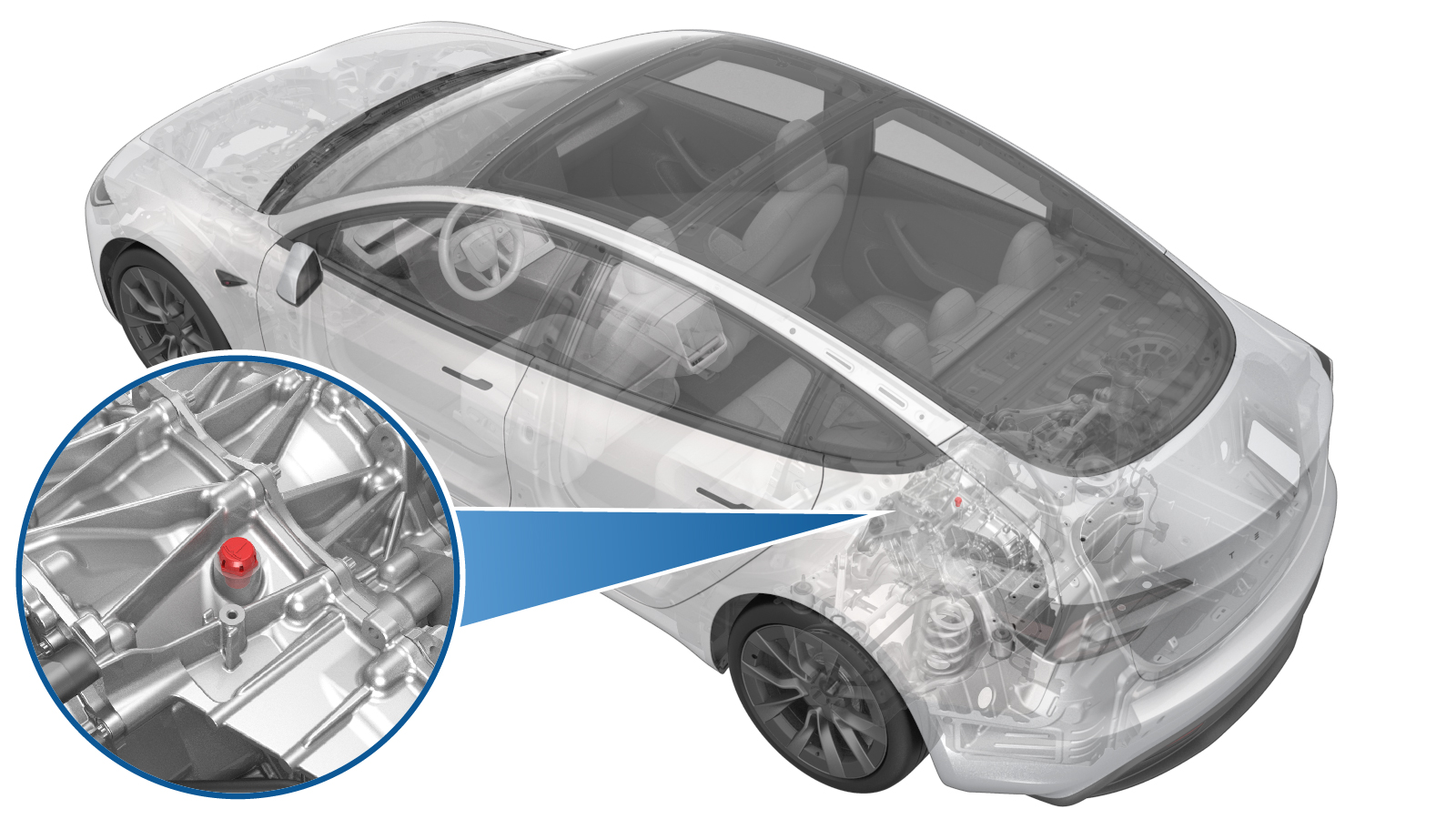
Mount - Rear Drive Unit - LH (3DU) (Remove and Replace)
 Correction code
4001020022
FRT
2.10
NOTE: Unless otherwise explicitly stated in the procedure, the correction code and FRT listed above reflect all of the work required to perform this procedure, including the linked procedures. Do not stack correction codes unless explicitly told to do so.
NOTE: See Flat Rate Times to learn more about FRTs and how they are created.
NOTE: See Personal Protection to make sure you
are wearing proper PPE when performing the procedure below.
NOTE: See Ergonomic Precautions for safe and healthy working practices.
Correction code
4001020022
FRT
2.10
NOTE: Unless otherwise explicitly stated in the procedure, the correction code and FRT listed above reflect all of the work required to perform this procedure, including the linked procedures. Do not stack correction codes unless explicitly told to do so.
NOTE: See Flat Rate Times to learn more about FRTs and how they are created.
NOTE: See Personal Protection to make sure you
are wearing proper PPE when performing the procedure below.
NOTE: See Ergonomic Precautions for safe and healthy working practices.
- 2023-12-11: Updated last step with cross reference to Alignment Requirement Tables.
Equipment:
- 1129348-00-A XP-10 Power Supply, XP-10
- 1099645-00-B Fixture, Subframe, Model 3
- 1140311-00-A Lever Lock, HV Connector, Model 3
Remove
- Raise and support the vehicle. See Raise Vehicle - 2 Post Lift.
- Remove the rear underhood apron. See Underhood Apron - Rear (Remove and Replace).
- Unlock the gateway. See Gateway Unlock.
- Touch on the touchscreen to start the routine and allow the routine to complete.
- Disconnect the LV power. See LV Power (Disconnect and Connect).
- Remove the 2nd row lower seat cushion. See Seat Cushion - 2nd Row (Remove and Replace).
- Perform the Vehicle HV Disablement Procedure. See Vehicle HV Disablement Procedure (Test/Adjust).
- Remove the LH and RH wheels. See Wheel Assembly (Remove and Install).
- Remove the rear aero shield panel. See Panel - Aero Shield - Rear (Remove and Replace).
- Remove the LH and RH rear suspension covers. See Cover - Rear Suspension - LH (Remove and Replace).
- Remove the rear fascia. See Fascia Assembly - Rear (Remove and Install).
-
Disconnect the RH subframe
harness electrical connector.
-
Use a clip prytool to
release the clip that attaches the RH subframe harness to the body.
-
Remove the nut that attaches
the rear drive unit ground strap to the body.
- Remove the stabilizer bar. See .
- Remove the rear HV battery skid plate. See Skid Plate - HV Battery - Rear (Remove and Replace).
- Remove the rear drive unit inlet hose. See Hose - Inlet - Rear Drive Unit Inverter (Remove and Replace).
- Remove the HV battery to the rear drive unit harness. See HV Harness - HV Battery to Rear Drive Unit (Remove and Replace).
- Position the rear subframe lifting tool beneath the rear subframe.
- Attach an air hose to the rear subframe lifting tool.
- With an assistant, raise the rear subframe lifting tool to support the rear subframe.
-
Loop the straps over the
rear subframe, hook the ends of the straps to the metal rings, and then pull
the straps tight to restrain the subframe to the rear subframe lifting
tool.
NoteLower the vehicle to give more slack to connect the straps to the rings, if necessary.
-
Mark the LH and RH rear
subframe bolts for realignment during installation.
Figure 1. LH shown; RH similar - Remove the LH and RH rear subframe front shear plates. See Shear Plate - Rear Subframe - LH (Remove and Replace).
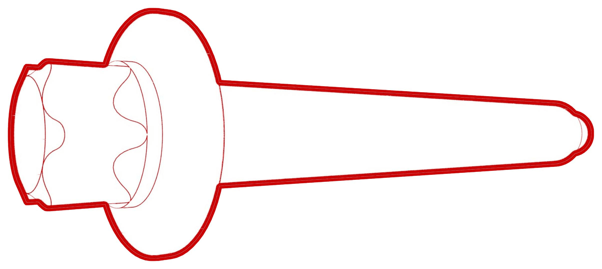
-
Remove and discard the LH
and RH bolts that attach the rear subframe to the body.
Figure 2. LH shown; RH similar - With an assistant, slowly lower the rear subframe and rear drive unit about 3.25 in (8.25 cm) from the vehicle.
- Tilt the subframe fixture forward to access the breather.
- Support the center of the rear drive unit with rubber or wood blocks.
-
Use a clip pry tool to
release the clip that attaches the rear drive unit ground strap to the rear
subframe.
-
Release the clip that
attaches the inverter to oil cooler hose to the LH mount.
-
Release the clip that
attaches the inverter to oil cooler hose to the inverter fitting, and remove
the hose from the inverter.
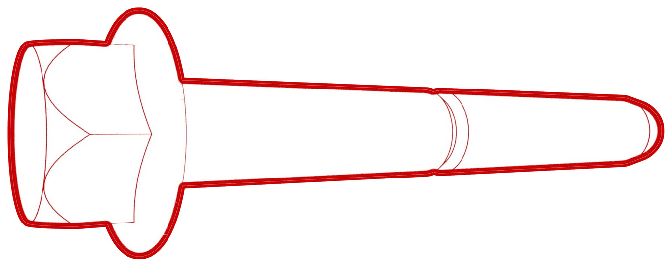
-
Remove and discard the bolt
that attach the LH mount to the subframe.
-
Remove and discard the bolts (x3) that
attach the LH mount to the rear drive unit, and remove the mount from the rear drive
unit.
Install
Replace all patchbolts.
Replace all nyloc nuts.
-
Install the LH rear drive unit mount
to the rear drive unit, and then hand-tighten new bolts (x3) (PN: 1111864-00-B) that
attach the mount to the rear drive unit.
-
Tighten the bolts in a two-step, counter-clockwise pattern, starting with the upper-right bolt.
 35 Nm (25.8 lbs-ft) +55 deg
 -
Install a new nut and bolt to attach the LH mount to the subframe.
 80 Nm (59.0 lbs-ft)
 -
Connect the inverter to oil
cooler hose to the inverter fitting, and then fasten the clip that attaches
the hose to the fitting.
CAUTIONPerform a push-pull test to verify that the hose is fully seated.
-
Fasten the clip that
attaches the inverter to oil cooler hose to the LH mount.
-
Fasten the clip that
attaches the rear drive unit ground strap to the rear subframe.
- Remove the rubber or wood blocks that support the center of the rear drive unit.
- Return the subframe fixture to its original position.
- Raise the rear subframe and rear drive unit.
-
Hand-tighten the LH and RH
bolts that attach the rear subframe to the body.
Figure 3. LH shown; RH similar - Install the LH and RH rear subframe front shear plates. See Shear Plate - Rear Subframe - LH (Remove and Replace).
- Position the subframe to the locations as marked during removal.
-
Torque the LH and RH bolts
that attach the rear subframe to the body, and then mark them with a paint
pen after torquing.
 165 Nm (121.7 lbs-ft)
Figure 4. LH shown; RH similar - Lower the rear subframe lifting tool from the vehicle.
- Disconnect the air hose from the rear subframe lifting tool.
- Remove the subframe lifting tool from the vehicle.
- Install the HV battery to the rear drive unit harness. See HV Harness - HV Battery to Rear Drive Unit (Remove and Replace).
- Install the rear drive unit inlet hose. See Hose - Inlet - Rear Drive Unit Inverter (Remove and Replace).
- Install the rear HV battery skid plate. See Skid Plate - HV Battery - Rear (Remove and Replace).
- Install the stabilizer bar. See .
-
Install the nut that
attaches the rear drive unit ground strap to the body.10 Nm (7.4 lbs-ft)
-
Fasten the clip that
attaches the RH subframe harness to the body.
-
Connect the RH subframe
harness electrical connector.
- Install the rear fascia. See Fascia Assembly - Rear (Remove and Install).
- Install the LH and RH rear suspension covers. See Cover - Rear Suspension - LH (Remove and Replace).
- Install the rear aero shield panel. See Panel - Aero Shield - Rear (Remove and Replace).
- Perform the vacuum refill procedure. See Cooling System - Vacuum Refill (Test/Adjust).
- Install the LH and RH wheels. See Wheel Assembly (Remove and Install).
- Install the 2nd row lower seat cushion. See Seat Cushion - 2nd Row (Remove and Replace).
- Connect the LV power. See LV Power (Disconnect and Connect).
- Install the rear underhood apron. See Underhood Apron - Rear (Remove and Replace).
- Install the LH and RH rear wheels. See Wheel Assembly (Remove and Install).
- Remove the vehicle from the 2 post lift. See .
- In this procedure, the front or rear subframe was removed and reinstalled. Therefore, refer to the Alignment Requirement tables to determine whether an EPAS alignment check (EC) or four wheel alignment check (AC) is necessary. If performed, add the alignment check/adjust as a separate activity. See Alignment Requirement - Suspension.