2025-11-25
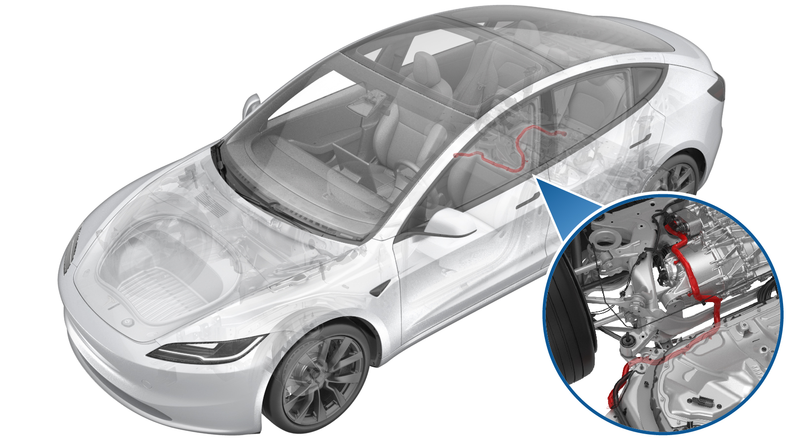
Hose - Outlet - Rear Drive Unit (Remove and Replace)
 Correction code
1830020042
FRT
0.72
NOTE: Unless otherwise explicitly stated in the procedure, the correction code and FRT listed above reflect all of the work required to perform this procedure, including the linked procedures. Do not stack correction codes unless explicitly told to do so.
NOTE: See Flat Rate Times to learn more about FRTs and how they are created.
NOTE: See Personal Protection to make sure you
are wearing proper PPE when performing the procedure below.
NOTE: See Ergonomic Precautions for safe and healthy working practices.
Correction code
1830020042
FRT
0.72
NOTE: Unless otherwise explicitly stated in the procedure, the correction code and FRT listed above reflect all of the work required to perform this procedure, including the linked procedures. Do not stack correction codes unless explicitly told to do so.
NOTE: See Flat Rate Times to learn more about FRTs and how they are created.
NOTE: See Personal Protection to make sure you
are wearing proper PPE when performing the procedure below.
NOTE: See Ergonomic Precautions for safe and healthy working practices.
Equipment:
- 1080568-00-A Fluid Catcher
- 1135762-00-A Kit, Svc Plug, Cooling Hose, Model 3
- 1065131-00-A Battery Coolant Drain Kit
- 1773595-00-A Laptop, RJ45 Ethernet Cable
- 1773092-00-A Diagnostic Harness Adapter - All Models
Remove
- Raise and support the vehicle. See Raise Vehicle - 2 Post Lift.
- Disconnect the LV battery power. See LV Power (Disconnect and Connect).
- Remove the HV battery rear skid plate. See Skid Plate - HV Battery - Rear (Remove and Replace).
-
Position the coolant drain container underneath the RH rear of the vehicle.
-
Disconnect the rear drive unit coolant
outlet hose from the powertrain return hose and plug the ends of both fittings as soon
as possible to avoid coolant loss.
NoteCoolant loss greater than 1L requires vacuum fill.
-
Release the clip and disconnect the
rear drive unit coolant outlet hose from the rear drive unit heat exchanger and plug the
ends of both fittings as soon as possible to avoid coolant loss.
NoteCoolant loss greater than 1L requires vacuum fill.
-
Release the clips (x3) to remove the rear drive unit coolant outlet hose from the
rear drive unit assembly.
Install
- Install the rear drive unit coolant outlet hose to the rear drive unit assembly.
-
Position the coolant drain container underneath the RH rear of the vehicle.
-
Remove the plugs on the ends of
fittings as quickly as possible to avoid coolant loss, and then install the rear drive
unit coolant outlet hose to the rear drive unit heat exchanger.
NotePerform a push-pull-push test on the fittings to make sure that they are secure.
-
Secure the rear drive unit coolant outlet hose clips (x3) to the rear drive unit
assembly.
-
Remove the plugs on the ends of
fittings as quickly as possible to avoid coolant loss, and then install the rear drive
unit coolant outlet hose to the powertrain return hose.
NotePerform a push-pull-push test on the fittings to make sure that they are secure.
- Remove the coolant drain container from underneath the RH rear of the vehicle.
- Install the HV battery rear skid plate. See Skid Plate - HV Battery - Rear (Remove and Replace).
- Lower the vehicle fully.
- Connect the LV battery power. See LV Power (Disconnect and Connect).
- Remove the coolant bottle cap and fill the coolant to the MAX line.
- Locally connect a laptop with Toolbox 3 to the vehicle. See Toolbox (Connect and Disconnect).
-
In Toolbox, click Actions/Autodiag, type
"Purge" into the search field, click TEST_VCFRONT_X_THERMAL-COOLANT-AIR-PURGEvia Service Mode:
- Thermal ➜ Actions ➜ Coolant Purge Stop or Coolant Purge Start
- Thermal ➜ Coolant System ➜ Coolant Purge Start
- Drive Inverter ➜ Front Drive Inverter Replacement ➜ Coolant Air Purge
- Drive Inverter ➜ Rear Drive Inverter Replacement ➜ Coolant Air Purge
- Drive Inverter ➜ Rear Left Drive Inverter Replacement ➜ Coolant Air Purge
- Drive Inverter ➜ Rear Right Drive Inverter Replacement ➜ Coolant Air Purge
- Drive Unit ➜ Front Drive Unit Replacement ➜ Coolant Air Purge
- Drive Unit ➜ Rear Drive Unit Replacement ➜ Coolant Air Purge
Note- Make sure that the vehicle is not in Drive. Putting the vehicle into Drive will stop this routine.
- The test lasts for approximately 10 mins.
- The speed in the test varies from 3500-6500 RPM (idle speed = ~1500 RPM) and the actuated valve varies between SERIES and PARALLEL.
- If the speed hovers at 7000 RPM, it indicates the pumps are air locked. Perform the vacuum fill again. Continue to add the coolant and purge until the coolant level reaches between the NOM and MAX Lines on the bottle.
- Inspect the coolant level and top off as necessary, and then install the coolant bottle cap.
- Disconnect Toolbox from the vehicle. See Toolbox (Connect and Disconnect).
- Install the rear underhood apron. See Underhood Apron - Rear (Remove and Replace).
- Remove the lift arms from below the vehicle.