Header - HV - Rear Drive Unit - HV Battery (Remove and Replace)
 Correction code
1601010042
FRT
0.66
NOTE: Unless otherwise explicitly stated in the procedure, the above correction code and FRT reflect all of the work required to perform this procedure, including the linked procedures. Do not stack correction codes unless explicitly told to do so.
NOTE: See Flat Rate Times to learn more about FRTs and how they are created. To provide feedback on FRT values, email ServiceManualFeedback@tesla.com.
NOTE: See Personal Protection to make sure wearing proper PPE when performing the below procedure.
NOTE: See Ergonomic Precautions for safe and healthy working practices.
Correction code
1601010042
FRT
0.66
NOTE: Unless otherwise explicitly stated in the procedure, the above correction code and FRT reflect all of the work required to perform this procedure, including the linked procedures. Do not stack correction codes unless explicitly told to do so.
NOTE: See Flat Rate Times to learn more about FRTs and how they are created. To provide feedback on FRT values, email ServiceManualFeedback@tesla.com.
NOTE: See Personal Protection to make sure wearing proper PPE when performing the below procedure.
NOTE: See Ergonomic Precautions for safe and healthy working practices.
- 1140311-00-A Lever Lock, HV Connector, Model 3
Only
technicians who have completed all required certification courses are permitted to
perform this procedure. Tesla recommends third party service provider technicians
undergo equivalent training before performing this procedure. For more information on
Tesla Technician requirements, or descriptions of the subject matter for third parties,
see HV Certification Requirements. Proper personal protective equipment (PPE) and insulating HV
gloves with a minimum rating of class 0 (1000V) must
be worn at all times a high voltage cable, busbar, or fitting is handled. Refer to Tech Note TN-15-92-003, High Voltage Awareness
Care Points
for additional safety
information.
Torque Specifications
| Description | Torque Value | Recommended Tools | Reuse/Replace | Notes |
|---|---|---|---|---|
| Nut that attaches the rear drive unit HV cable bracket to the HV battery |
 10 Nm (7.4 lbs-ft) |
|
Reuse | |
| Bolts (x2) that attach the HV header to the HV battery |
10 Nm (7.4 lbs-ft) |
|
Reuse |
Remove
- Perform Vehicle HV Disablement Procedure. See Vehicle HV Disablement Procedure (Test/Adjust).
- Remove the rear HV battery skid plate. See Skid Plate - HV Battery - Rear (Remove and Replace).
-
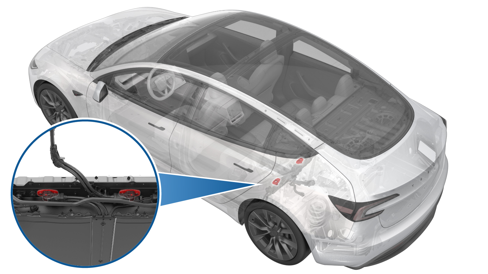
Remove the nut that attaches
the rear drive unit HV cable bracket to the HV battery.
TIpUse of the following tool(s) is recommended:
- 10 mm socket
- Cordless Ratchet/Impact Driver
-
Slide the red locking tab to
release, and then fully raise the black connector handle to disengage the
rear drive unit HV cable connector from the HV battery.
- Remove the rear drive unit HV cable connector from the HV battery header.
-
Remove the 5-lobe bolts (x2)
that attach the HV header to the HV battery.
TIpUse of the following tool(s) is recommended:
- 4 in extension
- External Torx E10 5-Lobe
- Ratchet/torque wrench
-
Insert the extractor tool into the HV header, push the tool handle in, and pull on the header to remove it from the HV battery.
WarningThe video(s) included in this procedure are meant as an overview for supplemental purposes only. Follow all of the steps listed in the procedure to avoid damage to components and/or personal injury.
-
Remove the clips (x6) that secure HC-Stak HV header retainer.
NoteInsert a pick into the metal retainer and pull the retainer away from HV to release clips.
Install
-
Install the HV header onto the HV battery.
NotePush the HV header upward till clips make click sound. Push and pull on the header to make sure it is secured.WarningThe video(s) included in this procedure are meant as an overview for supplemental purposes only. Follow all of the steps listed in the procedure to avoid damage to components and/or personal injury.
-
Install the 5-lobe bolts
(x2) that attach the HV header to the HV battery.10 Nm (7.4 lbs-ft)TIpUse of the following tool(s) is recommended:
- 4 in extension
- External Torx E10 5-Lobe
- Ratchet/torque wrench
-
Fully raise the handle on
the rear drive unit HV cable connector, and then install the HV connector
special tool onto the connector.
TIpUse of the following tool(s) is recommended:
- 1140311-00-A Lever Lock, HV Connector, Model 3
-
Use both hands to firmly
connect the rear drive unit HV cable connector to the HV battery
header.
CAUTIONMake sure that the connector fits the header squarely and tightly, and that both retention pins enter the handle.
- Remove the HV connector special tool from the HV battery rear drive unit connector.
-
While pressing the HV battery rear drive unit connector onto the HV battery header, fully lower the handle.
CAUTIONMake sure that the handle does not bind as it is lowered.
-
Slide the red locking tab to
lock the HV battery rear drive unit connector handle in the secured
position.
-
Verfiy that the HV battery rear drive unit connector is fully seated, and compare both sides of the connector that it is properly secured in place.
NoteAn improperly seated connector might lead to connector damage and rear drive unit problems later on.
-
Install the nut that
attaches the rear drive unit HV cable bracket to the HV battery.10 Nm (7.4 lbs-ft)TIpUse of the following tool(s) is recommended:
- 10 mm socket
- Cordless Ratchet/Impact Driver
- Install the rear HV battery skid plate. See Skid Plate - HV Battery - Rear (Remove and Replace).
- Connect LV power. See LV Power (Disconnect and Connect).