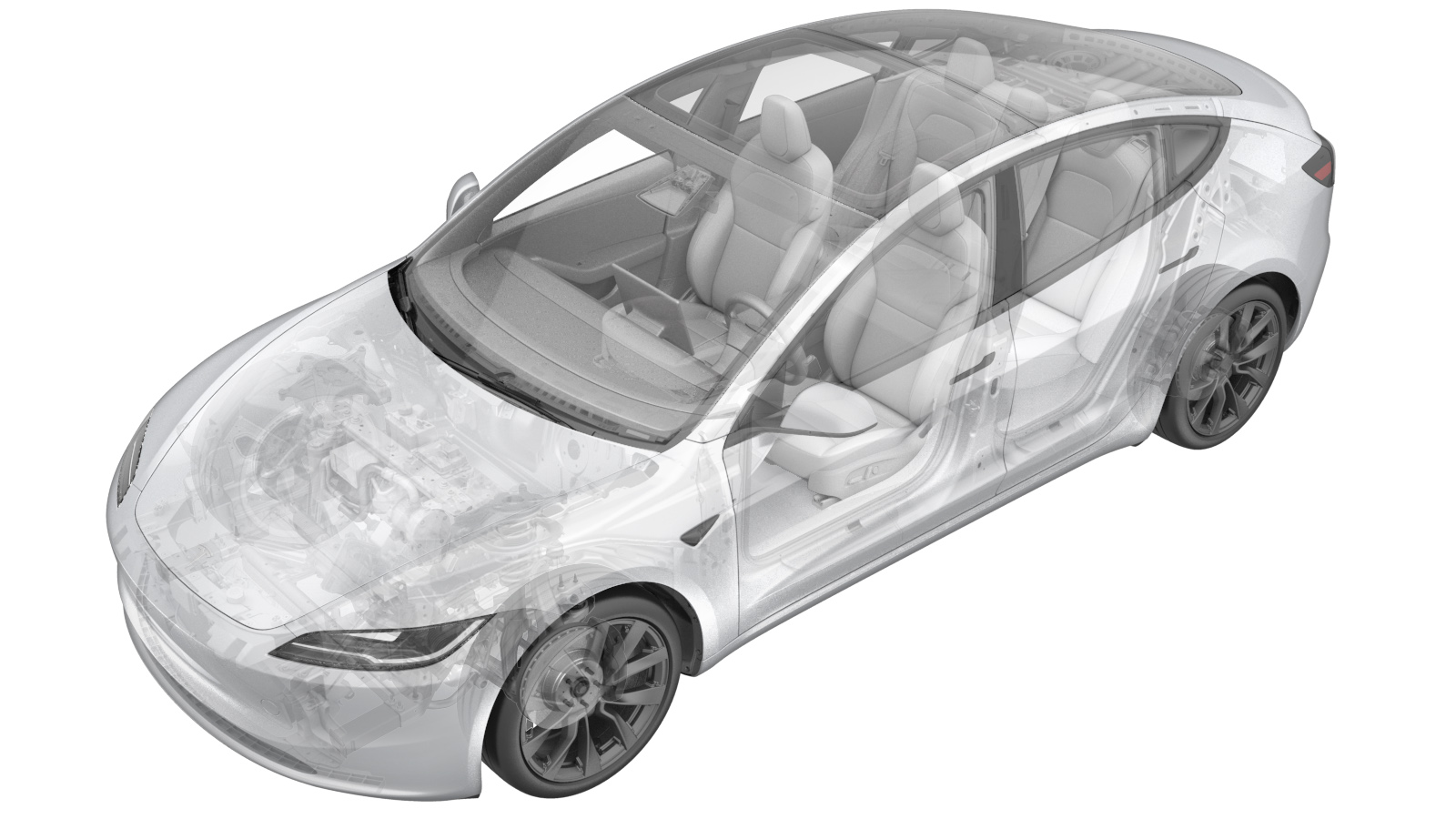
Camera - Front Fascia (Remove and Replace)
 Correction code
1722010012
FRT
0.18
NOTE: Unless
otherwise explicitly stated in the procedure, the above correction code and
FRT reflect all of the work required to perform this procedure, including
the linked procedures. Do
not stack correction codes unless explicitly told to do so.
NOTE: See Flat Rate
Times to learn more about FRTs and how
they are created. To provide feedback on FRT values, email ServiceManualFeedback@tesla.com.
NOTE: See Personal Protection
to make sure wearing proper PPE when performing the below procedure.
NOTE: See Ergonomic Precautions for safe and
healthy working practices.
- 2025-10-10: Released new procedure
Torque Specifications
| Description | Torque Value | Recommended Tools | Reuse/Replace | Notes |
|---|---|---|---|---|
| Screws (x2) that attach the front fascia camera cover to the front fascia assembly |
 4 Nm (2.9 lbs-ft) |
|
Reuse | |
| Screws (x2) that attach the front fascia camera to the cover |
 2 Nm (1.5 lbs-ft) |
|
Reuse |
Remove
- Open the LH front door and lower the LH front window.
- Place the vehicle in Service Mode by using the touchscreen. See Service Mode.
-
Remove the screws (x2) that attach the
front fascia camera cover to the front fascia assembly.
NoteUse of the following tool(s) is recommended:
- Torx T20 socket
-
Disconnect the front fascia camera
connector and nano nozzle.
-
Remove the screws (x2) that attach the
front fascia camera to the cover, and then remove the camera.
TIpUse of the following tool(s) is recommended:
- PH2 STUBBY PHILLIPS SCREWDRIVER
Install
-
Install the screws (x2) that attach
the front fascia camera to the cover.
 2 Nm (1.5 lbs-ft)TIpUse of the following tool(s) is recommended:
- PH2 STUBBY PHILLIPS SCREWDRIVER
-
Connect the front fascia camera
connector and nano nozzle.
-
Install the screws (x2) that attach
the front fascia camera cover to the front fascia assembly.
 4 Nm (2.9 lbs-ft)NoteUse of the following tool(s) is recommended:
- Torx T20 socket
- Locally connect a laptop with Toolbox 3 to the vehicle. See Toolbox (Connect and Disconnect).
-
In Toolbox, perform the following
steps.
- Click the Actions tab, type "Calibration Mode" into the search field, click PROC_DAS_X_ENTER-CALIBRATION-MODEvia Toolbox: (link), click Run, and allow the routine to complete.
- Click the Actions tab, type "Fascia Camera" into the search field, click PING-HTTP_DAS_FASCIA-CAMERA-SCRIPTvia Toolbox: (link), change the timeout to 100, click Run, and allow the routine to complete.
- Click the Actions tab, type "Calibration Mode" into the search field, click PROC_DAS_X_EXIT-CALIBRATION-MODEvia Toolbox: (link)via Service Mode Plus: Driver Assist ➜ Cameras ➜ Exit Factory Calibration Mode, click Run, and allow the routine to complete.
- Disconnect the laptop.
- Press and hold the Exit Service Mode button on the UI to exit Service Mode Plus.
- Raise the LH front window and close the LH front door.