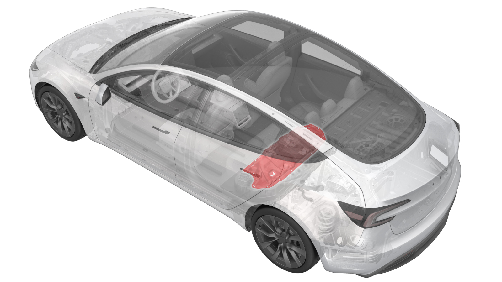
Ancillary Bay Cover (Remove and Replace)
 Correction code
1630010282
0.78
NOTE: Unless
otherwise explicitly stated in the procedure, the above correction code and
FRT reflect all of the work required to perform this procedure, including
the linked procedures. Do
not stack correction codes unless explicitly told to do so.
NOTE: See Flat Rate
Times to learn more about FRTs and how
they are created. To provide feedback on FRT values, email ServiceManualFeedback@tesla.com.
NOTE: See Personal Protection
to make sure wearing proper PPE when performing the below procedure.
NOTE: See Ergonomic Precautions for safe and
healthy working practices.
Correction code
1630010282
0.78
NOTE: Unless
otherwise explicitly stated in the procedure, the above correction code and
FRT reflect all of the work required to perform this procedure, including
the linked procedures. Do
not stack correction codes unless explicitly told to do so.
NOTE: See Flat Rate
Times to learn more about FRTs and how
they are created. To provide feedback on FRT values, email ServiceManualFeedback@tesla.com.
NOTE: See Personal Protection
to make sure wearing proper PPE when performing the below procedure.
NOTE: See Ergonomic Precautions for safe and
healthy working practices.
- 2025-10-13: Added warning at step to remove/install the ancillary bay cover to do this while standing outside the vehicle.
- 2025-03-13: Added high voltage controller rework steps and aluminum tape retrofit patch direction.
- 2025-03-13: Added image depicting the ancillary bay cover bolts torque sequence.
- 2025-02-19: Added steps to remove the incompatible HVC standoff to accommodate the newer ancillary bay cover design.
- 2024-07-30: Added information on installing a recycling warning label with CE marking and manufacturer information, if this was present on the ancillary bay cover being replaced.
- 1108781-SH-F: LABEL - RECYCLING WARNING - EU
High Voltage Awareness Care Pointsfor additional safety information.
Torque Specifications
| Description | Torque Value | Recommended Tools | Reuse/Replace | Notes |
|---|---|---|---|---|
| Bolts (x3) that attach the ancillary bay cover to the high voltage controller |
 5 Nm (3.7 lbs-ft) + 30 Degrees |
|
Reuse | |
| Bolts (x18) that attach the ancillary bay cover to the HV controller |
8 Nm (5.9 lbs-ft) |
|
Reuse |
CAUTION Use
an External Torx E10 5-Lobe socket that is not magnetized. Sockets
with magnets will not fully grip and can possibly strip the bolt
head. Note Torque these
fasteners in the sequence specified in the installation step. Note These bolts are
attached to the ancillary bay cover. |
Remove
- Disconnect the LV power. See LV Power (Disconnect and Connect).
- Remove the 2nd row lower seat cushion. See Seat Cushion - 2nd Row (Remove and Replace).
- Perform Vehicle HV Disablement Procedure. See Vehicle HV Disablement Procedure (Test/Adjust).
-
Disconnect the electrical harness from the high voltage controller connector.
NoteThe HV battery positive contactor and negative contactor open with a clunk sound.
-
Install the logic connector cap onto the high voltage controller connector to prevent mistaken reconnection and protect the connector.
-
Remove the bolts (x3) that attach the ancillary bay cover to the high voltage controller.
WarningThe video(s) included in this procedure are meant as an overview for supplemental purposes only. Follow all of the steps listed in the procedure to avoid damage to components and/or personal injury.TIpUse of the following tool(s) is recommended:
- 4 in extension
- Ratchet/torque wrench
- Torque wrench with angle measurement
- External Torx E10 5-Lobe
- Cordless Ratchet/Impact Driver
-
Remove the bolts (x18) that attach the ancillary bay cover to the HV battery.
TIpUse of the following tool(s) is recommended:
- Ratchet/torque wrench
- 10 in extension
- External Torx E10 5-Lobe
- Cordless Ratchet/Impact Driver
- Put on HV insulating gloves and leather outer gloves before continuing this procedure.
-
Remove the ancillary bay cover from the vehicle.
WarningRemove the ancillary bay cover from the vehicle while standing outside the vehicle to reduce the risk of falling into the open HV battery.
- Inspect whether HV insulators are present. If not present or partly present, use the Ancillary Bay Insulator kit and install the insulator caps onto the HV battery to cover live HV points. See Insulators - HV Battery (Remove and Install).
-
Visually inspect the condition of the ancillary bay cover gasket and the HV battery mating surface for cracks, cuts, gouges, abrasions, or any damage that could affect the seal.
NoteIf the damage to the gasket is severe, replace the ancillary bay cover. If there is minor damage (including paint) that might affect the seal, perform an ancillary bay air leak test when instructed to do so.NoteIf an ancillary bay air leak test is performed, add correction code 16100400 as a separate activity to the Service Visit.
Install
-
For Europe only: Check the ancillary bay cover that is being replaced for the presence of a recycling warning label that includes a CE marking and manufacturer information.
Figure 1. 1108781-BB-F shown, 1108781-SH-F similar - If the recycling warning label with CE marking and manufacturer information is not present on the ancillary bay cover being replaced, continue to the next step.
- If the recycling warning label with CE marking and manufacturer information is present on the ancillary bay cover being replaced:
- Note the area where the recycling warning label is affixed on the ancillary bay cover being replaced.
- Clean the corresponding area on the new ancillary bay cover with an IPA wipe and allow 1 minute dry time.
- Install a new recycling label with CE marking and Manufacturing Information (part number 1108781-SH-F) on the new ancillary bay cover.
-
If the old ancillary bay cover has
volcano brackets, and the replacement ancillary bay cover does not have the same brackets,
rework the High Voltage Controller (HVC) as required to achieve proper fitment between the
replacement cover and HVC. If the replacement cover has volcano brackets, skip to the next
step in this procedure.
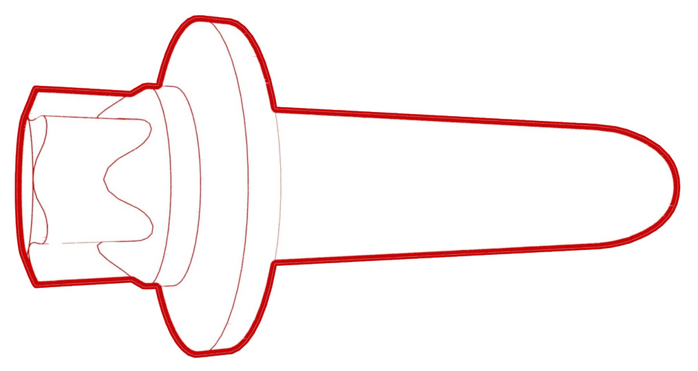
Figure 2. Replacement ancillary bay cover without volcano brackets Figure 3. Ancillary bay cover rework area; Cover shown installed for clarity Figure 4. HVC standoff to be removed; Ancillary bay cover shown removed for clarity -
Remove the bolts that attach the HVC
to the hinge tray, and then remove the controller from the vehicle.
 2 Nm (1.5 lbs-ft)
Figure 5. 5-Bolt HVC -
Install the HVC into the ancillary
bay, and then install the bolts that attach the HVC to the hinge tray.2 Nm (1.5 lbs-ft)
-
Remove the bolts that attach the HVC
to the hinge tray, and then remove the controller from the vehicle.
- Use IPA wipes to clean the ancillary bay cover gasket surface, and the mating surface of the HV battery.
-
If the aluminum tape retrofit patch is missing or damaged, remove the patch (if present), clean the area with an IPA wipe, apply another patch of aluminum tape, and wet out the patch with a silicone roller to set the adhesive.
TIpUse of the following tool(s) is recommended:
- 3M 425 Aluminum Foil Tape - 0601363
Figure 6. 5-Bolt to 4-Bolt Patch 50mm x 50mm Figure 7. 4-Bolt to 3-Bolt Patch 30mm x 30mm - Remove all insulator kit covers from the HV battery. See Insulators - HV Battery (Remove and Install).
-
Install the ancillary bay cover to the
HV battery.
WarningInstall the ancillary bay cover to the HV battery while standing outside the vehicle to reduce the risk of falling into the open HV battery.
- Remove the HV insulating gloves.
-
Install the bolts (x18) that attach
the ancillary bay cover to the HV battery in the sequence as shown.8 Nm (5.9 lbs-ft)CAUTIONUse an External Torx E10 5-Lobe socket that is not magnetized. Sockets with magnets will not fully grip and can possibly strip the bolt head.TIpUse of the following tool(s) is recommended:
- Ratchet/torque wrench
- 10 in extension
- External Torx E10 5-Lobe
- Cordless Ratchet/Impact Driver
-
Install the bolts (x3) that attach the ancillary bay cover to the high voltage controller.5 Nm (3.7 lbs-ft) + 30 DegreesTIpUse of the following tool(s) is recommended:
- 4 in extension
- Ratchet/torque wrench
- Torque wrench with angle measurement
- External Torx E10 5-Lobe
- Cordless Ratchet/Impact Driver
-
Remove the logic connector cap from the high voltage controller connector.
-
Connect the electrical harness to the high voltage controller connector.
- Install the 2nd row lower seat cushion. See Seat Cushion - 2nd Row (Remove and Replace).
- Connect the LV power. See LV Power (Disconnect and Connect).