2023-12-28
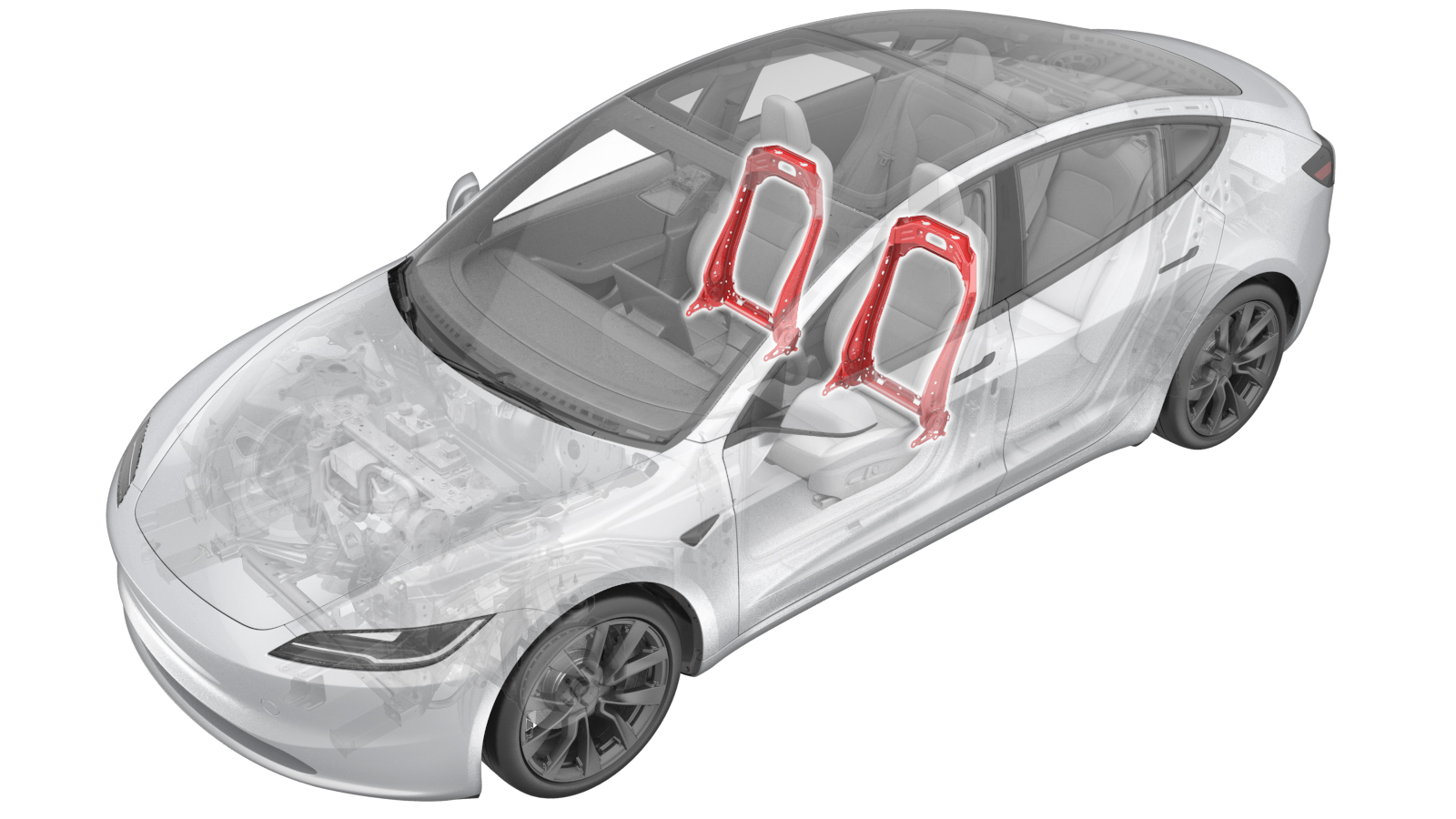
Frame - Back Rest - Front Seat (Remove and Replace)
 Correction code
1301010132
FRT
1.14
NOTE: Unless otherwise explicitly stated in the procedure, the correction code and FRT listed above reflect all of the work required to perform this procedure, including the linked procedures. Do not stack correction codes unless explicitly told to do so.
NOTE: See Flat Rate Times to learn more about FRTs and how they are created.
NOTE: See Personal Protection to make sure you
are wearing proper PPE when performing the procedure below.
NOTE: See Ergonomic Precautions for safe and healthy working practices.
Correction code
1301010132
FRT
1.14
NOTE: Unless otherwise explicitly stated in the procedure, the correction code and FRT listed above reflect all of the work required to perform this procedure, including the linked procedures. Do not stack correction codes unless explicitly told to do so.
NOTE: See Flat Rate Times to learn more about FRTs and how they are created.
NOTE: See Personal Protection to make sure you
are wearing proper PPE when performing the procedure below.
NOTE: See Ergonomic Precautions for safe and healthy working practices.
| Description | Torque Value | Recommended Tools | Reuse/Replace | Notes |
|---|---|---|---|---|
| Inboard and outboard bolts (x4) that attach the seat back frame to the seat cushion frame |
 43 Nm (31.7 lbs-ft) |
|
Replace | 1128435-00-C |
Remove
- Open both LH doors and lower both LH windows.
- Remove the LH front seat. See Seat Assembly - 1st Row - LH (Remove and Replace).
- Remove the headrest from the LH front seat. See Headrest - Front Seat - LH (Remove and Replace).
-
Rotate the seat to gain access to underside.
CAUTIONProtect the seat cushion from damage.
- Remove the LH front seatback shell assembly. See Shell - Seat Back - Front Seat - LH (Remove and Replace).
-
Disconnect the LH front seatback heater connector, and remove it from the seat
bottom.
NoteSlide the connector forward to release it from the seat bottom.
- Return the seat to upright position.
-
Remove the flaps that cover the outboard and inboard corners of the seatback
frame.
NotePull the flaps out of the metal tabs to release.
-
Release the seatback trim retainers
(x7) and a lock sheet from the seatback frame.
- Remove the backrest ventilation fan. See Blower - Backrest - Front Seat - LH (Remove and Replace).
-
Pull the seat upholstery away from the side air bag to gain access to the air bag
electrical connector, and then disconnect the seat side air bag connector.
NotePress and hold the black tabs on both sides and pull down to release the connector.
-
Pull the seat upholstery away from FSAB to gain access to the air bag electrical
connector, and then disconnect the seat FSAB connector.
NotePress and hold the black tabs on both sides and pull down to release the connector.
- Remove the power lumbar assembly from the seatback frame. See Lumbar Support - Backrest - Driver Seat (Remove and Replace).
- Remove the seat upholstery trim from the seatback frame. See Trim - Seat Back - Front Seat - LH (Remove and Replace).
-
Release the bayonets (x4) on the both sides of the two headrest post
guides, and then pull the two headrest post guides upward to remove them
from the seat back frame.
WarningThe video(s) included in this procedure are meant as an overview for supplemental purposes only. Follow all of the steps listed in the procedure to avoid damage to components and/or personal injury.
-
Release tabs (x4) to remove the
suspension plastic bases from the seatback frame.
NoteUse a small flat head screwdriver to release the tabs on the bases. If the bases are damaged, replace them.
- Remove the 1st row outboard sideshield. See Side Shield - Outboard - LH (Remove and Replace).
- Remove the 1st row outboard sideshield carrier. See Carrier - Side Shield - Outboard - 1st Row (Remove and Replace).
- Remove the 1st row inboard sideshield. See Side Shield - Inboard - LH (Remove and Replace).
- Remove the 1st row inboard sideshield carrier. See Carrier - Side Shield - Outboard - 1st Row (Remove and Replace).
-
Remove and discard the inboard and
outboard bolts (x4) that attach the seatback frame to the seat cushion frame.
TIpUse of the following tool(s) is recommended:
- Cordless Ratchet/Impact Driver
- Torx Plus T50 socket
- Flex head ratchet/flex head torque wrench
-
Rotate the seatback frame away from the cushion frame, and lift the seatback frame
straight up to remove it from the cushion frame.
Install
- Place the seatback frame onto the cushion frame for installation.
-
Install new inboard and outboard bolts
(x4) (1128435-00-C) to attach the seatback frame to the seat cushion frame.43 Nm (31.7 lbs-ft)TIpUse of the following tool(s) is recommended:
- Cordless Ratchet/Impact Driver
- Torx Plus T50 socket
- Flex head ratchet/flex head torque wrench
- Install the 1st row outboard sideshield carrier. See Carrier - Side Shield - Outboard - 1st Row (Remove and Replace).
- Install the 1st row outboard sideshield. See Side Shield - Outboard - LH (Remove and Replace).
- Install the 1st row inboard sideshield carrier. See Carrier - Side Shield - Outboard - 1st Row (Remove and Replace).
- Install the 1st row inboard sideshield. See Side Shield - Inboard - LH (Remove and Replace).
-
Secure the tabs (x4) to attach the
suspension plastic bases to the seatback frame.
NoteEnsure that the tabs are installed in place. If the bases are damaged, replace them.
-
Install the bayonets (x4) that attach the headrest post guides to the seat
back frame.
- Install the driver seat seatback and foam onto the seatback frame. See Trim - Seat Back - Front Seat - LH (Remove and Replace).
- Install the power lumbar assembly to the seatback frame. See Lumbar Support - Backrest - Driver Seat (Remove and Replace).
-
Connect the LH front seat side air bag connector.
-
Connect the LH front seat FSAB connector.
- Install the backrest ventilation fan. See Blower - Backrest - Front Seat - LH (Remove and Replace).
-
Install the flaps that cover the
outboard and inboard corners of the seatback frame.
NotePull the flaps out of the metal tabs to release.
-
Secure the lock sheet and the seatback
trim retainers (x7) onto the seatback frame.
-
Position the driver seat
back shell onto the seat back, and then fasten the clips that attach the
seat back shell to the seat back.
NoteInstall the lower clips first, and then rotate the shell up into position. Apply light pressure to ensure the seat back shell is fully seated.WarningThe video(s) included in this procedure are meant as an overview for supplemental purposes only. Follow all of the steps listed in the procedure to avoid damage to components and/or personal injury.
- Install the headrest to the LH front seat. See Headrest - Front Seat - LH (Remove and Replace).
-
Rotate the seat to gain access to
underside.
CAUTIONProtect the seat cushion from damage.
-
Install the front seatback heater
connector to the seat bottom and connect the connector.
NoteSlide the connector onto the seat frame clip to secure.
-
Hook the strap clips (x2) onto the
driver seatback shell assembly.
NoteEnsure the straps are tight for proper fit and installation.
- Return the seat to upright position.
-
Install the LH front seat. See Seat Assembly - 1st Row - LH (Remove and Replace).
NoteNo need to reinstall the firmware.
- Raise both LH windows and close both LH doors.