2023-10-17
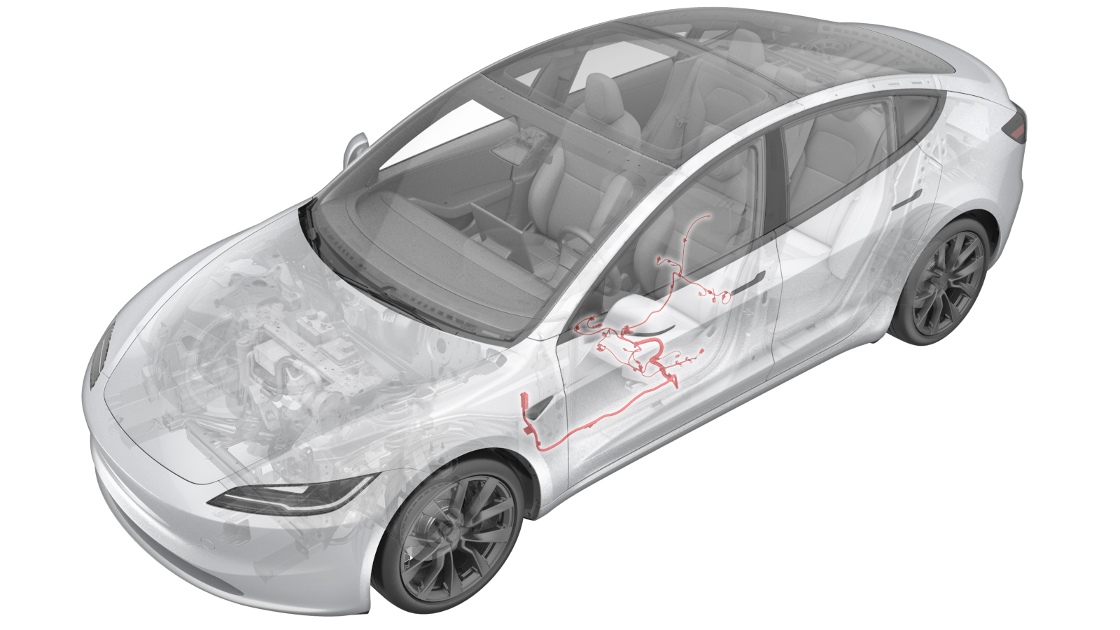
Harness - 1st Row Seat - LH (Remove and Replace)
 Correction code
1710060012
FRT
0.84
NOTE: Unless otherwise explicitly stated in the procedure, the correction code and FRT listed above reflect all of the work required to perform this procedure, including the linked procedures. Do not stack correction codes unless explicitly told to do so.
NOTE: See Flat Rate Times to learn more about FRTs and how they are created.
NOTE: See Personal Protection to make sure you
are wearing proper PPE when performing the procedure below.
NOTE: See Ergonomic Precautions for safe and healthy working practices.
Correction code
1710060012
FRT
0.84
NOTE: Unless otherwise explicitly stated in the procedure, the correction code and FRT listed above reflect all of the work required to perform this procedure, including the linked procedures. Do not stack correction codes unless explicitly told to do so.
NOTE: See Flat Rate Times to learn more about FRTs and how they are created.
NOTE: See Personal Protection to make sure you
are wearing proper PPE when performing the procedure below.
NOTE: See Ergonomic Precautions for safe and healthy working practices.
Remove
- Remove the rear underhood apron. See Underhood Apron - Rear (Remove and Replace).
- Remove the LH intrument panel end cap. See End Cap - Instrument Panel - LH (Remove and Replace).
- Remove the LH lower A-pillar trim. See Trim - A-Pillar - Lower - LH (Remove and Replace).
- Disconnect LV power. See LV Power (Disconnect and Connect).
- Remove the driver seat. See Seat Assembly - 1st Row - LH (Remove and Replace).
- Remove the driver headrest trim. See Headrest - Front Seat - LH (Remove and Replace).
- Remove the driver seat back shell. See Shell - Seat Back - Front Seat - LH (Remove and Replace).
-
Remove the upper and lower
flaps covering the outboard side of the seat back frame.
NotePull the flaps out of the metal retaining tabs to release them.
-
Remove the upper and lower
flaps covering the inboard side of the seat back frame.
NotePull the flaps out of the metal retaining tabs to release them.
-
Release the seat back trim retainers from the seat back frame.
-
Disconnect the electrical
harness from the backrest ventilation fan connector.
-
Pull the seat upholstery
away from the airbag to gain access to the electrical connector and then
press and hold the black tabs on both sides and pull them down to disconnect
the airbag electrical connector.
-
Pull the seat upholstery away from the FASB to gain access to the
electrical connector and then press and hold the black tabs on both sides
and pull them down to disconnect the airbag electrical connector.
-
Remove the harness clip
securing the air bag pigtail to the seat back frame with a clip
prytool.
-
Use a trim tool to release
the clips (x4) that attach the electrical harness to the seat frame.
-
Remove the harness clip securing the FSAB pigtail to the seat back frame
with a clip prytool.
-
Disconnect the electrical
harness from the recliner motor connector.
-
Disconnect the electrical
harness from the lumbar valve pack and ECU.
-
Disconnect the electrical
harness from the lumbar pump connector.
-
Remove the driver seat outboard side shield. See Side Shield - Outboard - LH (Remove and Replace).
NoteDo not remove the seat cushion switch button, seat recliner switch button and the 8-way switch from the driver seat outboard side shield.
-
Release the safety lock, and then disconnect the driver seatbelt
pretensioner electrical connector.
-
Release the seatbelt pretensioner harness from the harness bracket.
NoteMove the harness bracket forward and then backward to remove.
-
Remove the clips (x2) that
attach the driver seat switch harness to the seat cushion frame.
-
Rotate the seat to gain access to the seat underside.
-
Unhook the straps for the lower section of the seat back and move the seat
back flap away from the underside of the seat.
-
Disconnect the seat cushion
ventilation fan connector.
-
Disconnect the seat back heater connector.
-
Remove the seat back harness connector from the seat bottom.
-
Disconnect the heat pad connector.
-
Release the seat occupied sensor connector from the seat harness
bracket.
-
Disconnect the seat occupied sensor and set the sensor harness pigtail
aside.
-
Remove the clip that attaches the harness to the seat underside.
NoteThe clip is next to the seat heater connectors.
-
Remove the clips (x2) that attach the track motor harness to the track
motor housing.
-
Disconnect the tilt motor connector.
-
Disconnect the lift motor connector.
-
Disconnect LH front seat track motor connector.
-
Release the clip that attaches the LH front seat harness to the outboard
seat track.
-
Disconnect the seat belt buckle connector.
NoteMove the connector bracket backward and then forward to remove the connector.WarningThe video(s) included in this procedure are meant as an overview for supplemental purposes only. Follow all of the steps listed in the procedure to avoid damage to components and/or personal injury.
-
Release the clips (x2) that attach the seat belt buckle connector harness
to the seat cushion frame.
-
Remove the seat harness bracket from the seat frame.
NoteFlip the seat forward to access clips, and then use the 90 degree tip to release clips (x3).
-
With the wire harness bracket as the center, route the wire harness around
the seat frame and keep the harness away from the seat.
-
Remove the seat harness assembly from the seat frame.
Install
-
Position the new seat
harness for installation.
NoteWith the wire harness bracket as the center, route the harness under the lift motor and tilt motor placing the harness legs in the correct locations. Harness clips will be installed later.
-
Install the seat harness
bracket to the seat base assembly.
-
Install the clips (x2) that attach the seat belt buckle connector harness
to the seat cushion frame.
-
Connect the seat belt buckle connector.
NoteFirst move the connector bracket backward, and then move the connector bracket forward to install.
-
Install the clip that attaches the LH front seat harness to the outboard
seat track.
-
Connect the LH front seat track motor connector.
-
Connect the lift motor connector.
-
Connect the tilt motor connector.
-
Install the clips (x2) that attach the track motor harness to the track
motor housing.
-
Install the clip that attaches the harness to the seat underside.
NoteThe clip is next to the seat heater connectors.
-
Connect the heat pad connector.
-
Connect the seat occupied sensor and install the sensor onto the seat
harness bracket.
NoteEnsure the harness is not routed between the cushion and frame to avoid friction.
-
Install the seat back harness connector to the seat bottom.
NoteSlide the connector onto the seat frame clip to secure.
-
Connect the seat back heater harness connector.
-
Connect the seat cushion ventilation fan connector.
-
Rotate the seat back to the upright position.
-
Install the clips (x2) that attach the driver seat switch harness to the
seat cushion frame.
-
Install the seatbelt pretensioner harness bracket.
NoteMove the harness bracket backward, and then move it backward to install.
-
Connect the driver seatbelt pretensioner electrical connector.
NoteEnsure the connector safety lock is engaged.
-
Install the driver seat outboard side shield. See Side Shield - Outboard - LH (Remove and Replace).
NoteIt is not necessary to install the seat cushion switch button, seat recliner switch button and the 8-way switch to the driver seat outboard side shield as they were not removed during the removal.
-
Connect the lumbar pump electrical connector.
-
Connect the lumbar valve pack and ECU electrical connector.
-
Connect the recliner motor electrical connector.
-
Connect the backrest ventilation fan electrical connector.
-
Install the harness clip securing the FSAB pigtail to the seat back
frame.
-
Install the clips (x4) that
attach the electrical harness to the seat frame.
-
Install the harness clip securing the air bag pigtail to the seat back
frame.
-
Connect the driver seat FSAB
electrical connector.
-
Connect the driver seat side
air bag electrical connector.
-
Install the lower and upper flaps covering the inboard side of the seat
back frame.
NotePull the flaps over the metal retaining tabs to secure them.
-
Install the lower and upper flaps covering the outboard side of the seat
back frame.
NotePull the flaps over the metal retaining tabs to secure them.
-
Secure the seat back trim retainers onto the seat back frame.
- Install the driver seat back shell. See Shell - Seat Back - Front Seat - LH (Remove and Replace).
- Install the driver headrest trim. See Headrest - Front Seat - LH (Remove and Replace).
- Install the driver seat. See Seat Assembly - 1st Row - LH (Remove and Replace).
- Connect LV power. See LV Power (Disconnect and Connect).
- Install the LH lower A-pillar trim. See Trim - A-Pillar - Lower - LH (Remove and Replace).
- Install the LH instrument panel end cap. See End Cap - Instrument Panel - LH (Remove and Replace).
- Install the rear underhood apron. See Underhood Apron - Rear (Remove and Replace).