2026-05-15
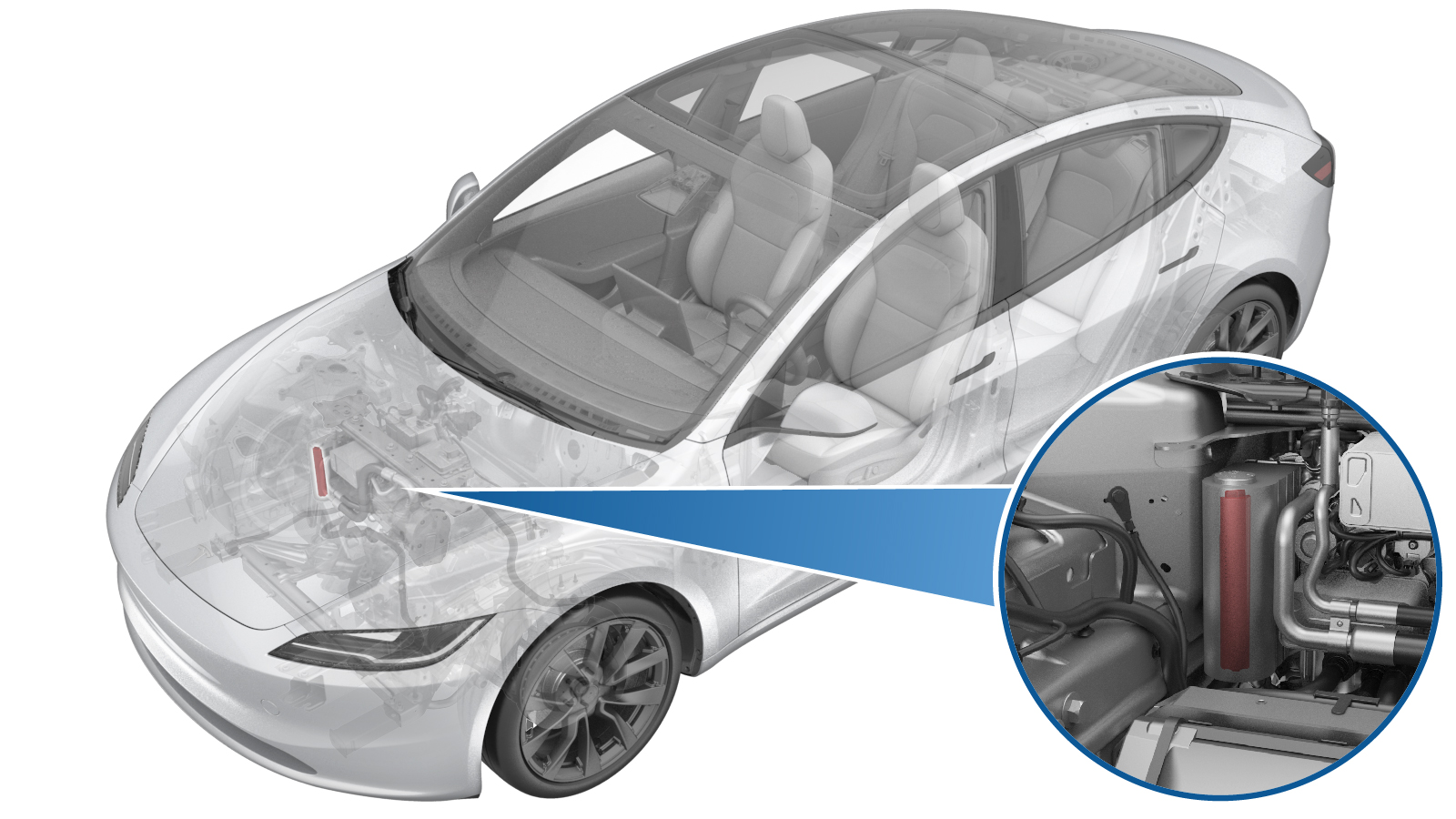
Desiccant (Remove and Replace)
 Correction code
1840010052
FRT
0.30
NOTE: Unless otherwise explicitly stated in the procedure, the correction code and FRT listed above reflect all of the work required to perform this procedure, including the linked procedures. Do not stack correction codes unless explicitly told to do so.
NOTE: See Flat Rate Times to learn more about FRTs and how they are created.
NOTE: See Personal Protection to make sure you
are wearing proper PPE when performing the procedure below.
NOTE: See Ergonomic Precautions for safe and healthy working practices.
Correction code
1840010052
FRT
0.30
NOTE: Unless otherwise explicitly stated in the procedure, the correction code and FRT listed above reflect all of the work required to perform this procedure, including the linked procedures. Do not stack correction codes unless explicitly told to do so.
NOTE: See Flat Rate Times to learn more about FRTs and how they are created.
NOTE: See Personal Protection to make sure you
are wearing proper PPE when performing the procedure below.
NOTE: See Ergonomic Precautions for safe and healthy working practices.
- 2026-05-15: Removed the first responder loop steps and Thermal/HVAC performance test steps.
- 2025-06-09: Updated the special tools for removing the accumulator cap.
- 2025-05-08: Added additional step to check refrigerant system pressure on the touchscreen after refrigerant recovery.
- 2024-09-27: Updated the UI routines and added note on adding correction code for refrigerant recovery/recharge 18200102 as a separate activity to the service visit.
- 2024-09-10: Added warnings to wear suitable protective clothing, consisting of face and eye protection, heat-proof gloves, rubber boots and apron or waterproof overalls must be worn when carrying out operations on the air conditioning system.
- 2024-06-12: Added caution for Schrader valves.
- 2024-04-02: Added reminding of checking the pressure of A/C system before opening the accumulator.
- 2024-04-07: Added reminding of wearing PPEs.
Equipment:
- 1985068-00-A - Female to Female Threaded Adapter
- 1081547-00-B - Small Slide Hammer
Warning
HFO-R1234yf and R134a are considered
hazardous and, if handled incorrectly, can cause serious injury. Suitable personal
protective equipment, consisting of face and eye protection, safety glasses, face
shield, heat-proof gloves, chemical resistant gloves, rubber boots and apron or
waterproof overall must be worn when carrying out operations on the air conditioning
system.
CAUTION
Thermal management components operate
under very tight specifications and can malfunction if Service procedures are not
carefully followed. DO NOT rely on
past experience with other thermal management systems; read through the Service Manual and
do not deviate from the instructions.
Note
This procedure requires the A/C
Refrigerant (Recovery and Recharge) procedure to be performed. If not already
automatically added to the Service Visit, add correction code 18200102 as a
separate correction within the same activity to the Service Visit.
Torque Specifications
| Description | Torque Value | Recommended Tools | Reuse/Replace | Notes |
|---|---|---|---|---|
| Accumulator dust cap |
 NaN Nm (NaN lbs-ft) |
|
Replace |
Remove
- Set up the AC machine.
- Remove the underhood storage unit. See Underhood Storage Unit (Remove and Replace).
-
Perform the following
routine using Service Mode or Toolbox (see 0005 - Service Modes):
PROC_VCFRONT_X_START-THERMAL-FILL-DRAINvia Service Mode:
- Thermal ➜ Actions ➜ Start Thermal Fill/Drain
- Thermal ➜ Coolant System ➜ Start Coolant Fill/Drain
- Thermal ➜ Refrigerant System ➜ Start Refrigerant Fill/Drain
- Drive Inverter ➜ Front Drive Inverter Replacement ➜ Start Fluid Fill/Drain
- Drive Inverter ➜ Rear Drive Inverter Replacement ➜ Start Fluid Fill/Drain
- Drive Unit ➜ Front Drive Unit Replacement ➜ Start Coolant Fill/Drain
- Drive Unit ➜ Rear Drive Unit Replacement ➜ Start Coolant Fill/Drain
NoteSelect "X" at top right of window to close once complete, Thermal Fluid Fill/Drain routine has a 5 hour time limit, After 5 hours EXV's will close and routine must be performed again, Verify EXV positions are open VIA Garage >Thermal > Refrigerant loop EXV, Verify LCC, CC Left, Evap, CC Right, Chiller are all at ~100%. Recirc is at ~20%, LCC Solenoid is OPENED -
Recover the A/C refrigerant. See A/C Refrigerant (Recovery and Recharge) (Restore).
WarningHFO-R1234yf and R134a are considered hazardous and, if handled incorrectly, can cause serious injury. Suitable personal protective equipment, consisting of face and eye protection, safety glasses, face shield, heat-proof gloves, chemical resistant gloves, rubber boots and apron or waterproof overall must be worn when carrying out operations on the air conditioning system.NoteMake sure there is no overpressure in the A/C system before performing the following steps. Failure to do so may result in damage to components and/or personal injury.
-
On the touchscreen, make sure that the refrigerant system pressure is at atmospheric level (approx. 1 bar).
NoteOn the touchscreen, touch .
- On the touchscreen, tap to power off the vehicle.
- Wear appropriate personal protective equipment (PPE).
- Remove A/C hoses from the vehicle.
-
Carefully depress the Schrader valves (x2) to level out any pressure difference between the A/C system pressure and the actual ambient atmospheric pressure.
CAUTIONMake sure to depress both Schrader valves. Failure to do so may result in injury.
-
If present, remove and discard the
dust cap from the accumulator.
TIpUse of the following tool(s) is recommended:
- Torx T30 bit
- 3 in extension
- Flex head ratchet/flex head torque wrench
-
Use snap ring pliers to remove and
discard the accumulator cap snap ring.
WarningWear the Face Shield throughout the entire process to protect against foreign objects flying out under pressure.WarningThe video(s) included in this procedure are meant as an overview for supplemental purposes only. Follow all of the steps listed in the procedure to avoid damage to components and/or personal injury.
-
Thread the adapter onto the slide
hammer, and then thread the slide hammer onto the accumulator cap. Use the adapter and
the slide hammer to remove and discard the accumulator cap.
WarningWear the Face Shield throughout the entire process to protect against foreign objects flying out under pressure.TIpUse of the following tool(s) is recommended:
- 1985068-00-A - Female to Female Threaded Adapter
- 1081547-00-B - Small Slide Hammer
-
Use needle nose pliers to remove the
desiccant bag from the accumulator.
- Weigh the desiccant bag. This is considered the "wet weight."
- Determine the "dry weight" of the desiccant bag: Inspect the bag for a label that contains the Part Number (P), Serial Number (S), and Dry Weight (W). If the label is missing, or if the dry weight is not visible, assume the dry weight is 90.4 grams.
- Subtract the dry weight from the wet weight. This is the amount of oil that must be added to the system in addition to the oil that was removed during refrigerant recovery. Note this amount for later.
Install
-
Install the desiccant bag in the
accumulator.
WarningThe video(s) included in this procedure are meant as an overview for supplemental purposes only. Follow all of the steps listed in the procedure to avoid damage to components and/or personal injury.NoteMake sure the tab on the desiccant bag faces upward.
-
Lubricate the new accumulator cap
O-rings with the appropriate A/C oil. See Fluids and Capacities for A/C oil specifications. Then
install the cap on the accumulator.
-
Use the snap ring pliers to install
the new accumulator cap snap ring.
WarningWear the Face Shield throughout the entire process to protect against foreign objects flying out under pressure.NoteMake sure the snap ring is fully seated in the groove on the inside of the accumulator bore.
-
If equipped, hand-tighten the new dust
cap to the accumulator.
TIpUse of the following tool(s) is recommended:
- Torx T30 bit
- 3 in extension
- Flex head ratchet/flex head torque wrench
-
Perform the vacuum leak test and
refill A/C refrigerant. See A/C Refrigerant (Recovery and Recharge) (Restore).
NoteInject the amount of oil that was lost to:
- Removal of the old desiccant bag. See step 16.
- Refrigerant recovery. See A/C Refrigerant (Recovery and Recharge) (Restore).
CAUTIONDO NOT forget to inject the amount of oil that was lost to removal of the old desiccant bag. Failure to do so might cause catastrophic damage to the thermal system. - Unlock the vehicle gateway. See Gateway Unlock.
-
Perform the following
routine using Service Mode or Toolbox (see 0005 - Service Modes):
TEST-SELF_VCFRONT_X_HEAT-PUMP-COMMISSIONINGvia Service Mode:Thermal ➜ Refrigerant System ➜ Commission Heat Pumpvia Service Mode Plus:Drive Inverter ➜ Front Drive Inverter Replacement ➜ Heatpump commissioningvia Toolbox:(link)
NoteIf this routine is not run after entering Thermal Drain/Fill mode, the AC compressor operation will be blocked, Select ‘X’ at top right of window to close once complete.
- Exit Service Mode through UI. See Service Mode.
- Install the underhood storage unit. See Underhood Storage Unit (Remove and Replace).