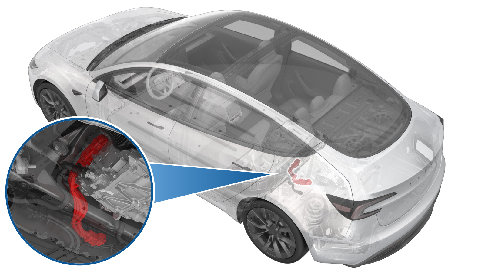
HV Harness - HV Battery to Rear Drive Unit (Remove and Replace)
 Correction code
4450010092
FRT
0.78
NOTE: Unless otherwise explicitly stated in the procedure, the correction code and FRT listed above reflect all of the work required to perform this procedure, including the linked procedures. Do not stack correction codes unless explicitly told to do so.
NOTE: See Flat Rate Times to learn more about FRTs and how they are created.
NOTE: See Personal Protection to make sure you
are wearing proper PPE when performing the procedure below.
NOTE: See Ergonomic Precautions for safe and healthy working practices.
Correction code
4450010092
FRT
0.78
NOTE: Unless otherwise explicitly stated in the procedure, the correction code and FRT listed above reflect all of the work required to perform this procedure, including the linked procedures. Do not stack correction codes unless explicitly told to do so.
NOTE: See Flat Rate Times to learn more about FRTs and how they are created.
NOTE: See Personal Protection to make sure you
are wearing proper PPE when performing the procedure below.
NOTE: See Ergonomic Precautions for safe and healthy working practices.
Equipment:
- 1140311-00-A Lever Lock, HV Connector, Model 3
Only
technicians who have completed all required certification courses are permitted to
perform this procedure. Tesla recommends third party service provider technicians
undergo equivalent training before performing this procedure. For more information on
Tesla Technician requirements, or descriptions of the subject matter for third parties,
see HV Certification Requirements. Proper personal protective equipment (PPE) and insulating HV
gloves with a minimum rating of class 0 (1000V) must
be worn at all times a high voltage cable, busbar, or fitting is handled. Refer to Tech Note TN-15-92-003, High Voltage Awareness
Care Points
for additional safety
information.
Remove
- Raise and support the vehicle. See Raise Vehicle - 2 Post Lift.
- Remove the rear underhood apron. See Underhood Apron - Rear (Remove and Replace).
- Disconnect the LV power. See LV Power (Disconnect and Connect).
- Remove the 2nd row lower seat cushion. See Seat Cushion - 2nd Row (Remove and Replace).
- Perform the Vehicle HV Disablement Procedure. See Vehicle HV Disablement Procedure (Test/Adjust).
- Remove the rear aero shield panel. See Panel - Aero Shield - Rear (Remove and Replace).
- Remove the rear HV battery skid plate. See Skid Plate - HV Battery - Rear (Remove and Replace).
- Remove the rear drive unit inlet hose. See Hose - Inlet - Rear Drive Unit Inverter (Remove and Replace).
-
Remove the bolt that
attaches the HV battery to rear drive unit harness bracket to the rear drive
unit inverter.
TIpUse of the following tool(s) is recommended:
- 10 mm socket
- Cordless hex driver
WarningThe video(s) included in this procedure are meant as an overview for supplemental purposes only. Follow all of the steps listed in the procedure to avoid damage to components and/or personal injury. -
Remove the nut that attaches
the HV battery to rear drive unit harness bracket to the HV battery.
TIpUse of the following tool(s) is recommended:
- 6 in nutsetter + 10 mm magnetic deep
- Cordless hex driver
-
Slide the release to unlock
the HV battery rear drive unit connector handle of the rear drive unit to HV
battery harness from the secured position.
-
Fully raise the handle on
the HV battery rear drive unit connector.
- Disconnect the electrical connector that attaches the rear drive unit HV harness to the HV battery.
- Repeat step 11 through step 13 on the other side of the rear drive unit HV harness.
-
Move the HV battery to rear
drive unit harness down and out between the rear subframe and the HV
battery.
NoteRotate the harness as necessary to move the rear drive unit inverter connector end of the harness between the subframe and HV battery.
Install
-
Move the rear drive unit
inverter connector end of the HV battery to rear drive unit harness up and
in between the rear subframe and the HV battery.
NoteRotate the harness as necessary to move the connector between the subframe and HV battery.
- Fully raise the handle on the electrical connector that attaches the rear drive unit HV harness to the rear drive unit.
-
Install the HV connector special tool
onto the electrical connector that attaches the rear drive unit HV harness to the rear
drive unit.
-
Use both hands to firmly connect the
electrical connector that attaches the rear drive unit HV harness to the rear drive
unit.
CAUTIONMake sure that the connector fits the header squarely and tightly, and that both retention pins enter the handle.
- Remove the HV connector special tool from the electrical connector that attaches the rear drive unit HV harness to the rear drive unit.
-
While pressing the
electrical connector that attaches the rear drive unit HV harness to the
rear drive unit., fully lower the handle.
CAUTIONMake sure that the handle does not bind as it is lowered.
-
Slide the release to lock
the electrical connector that attaches the rear drive unit HV harness to the
rear drive unit in the secured position.
-
Verify that the electrical
connector is fully seated, and compare both sides of the connector that it
is properly secured in place.
NoteAn improperly seated connector might lead to connector damage and rear drive unit problems later on.
- Repeat step 2 through step 8 on the other side of the rear drive unit HV harness.
-
Install the nut that
attaches the HV battery to rear drive unit harness bracket to the HV
battery.
 10 Nm (7.4 lbs-ft)TIpUse of the following tool(s) is recommended:
- 10 mm socket
- Cordless hex driver
- Ratchet/torque wrench
-
Install the bolt that
attaches the HV battery to rear drive unit harness bracket to the rear drive
unit inverter.6 Nm (4.4 lbs-ft)TIpUse of the following tool(s) is recommended:
- 10 mm socket
- Cordless hex driver
- Ratchet/torque wrench
- Move the end of the rear drive unit inlet hose up and in between the HV battery and rear subframe, and then up and in between the rear drive unit and rear subframe.
- Install the rear drive unit inlet hose. See Hose - Inlet - Rear Drive Unit Inverter (Remove and Replace).
- Install the rear HV battery skid plate. See Skid Plate - HV Battery - Rear (Remove and Replace).
- Install the rear aero shield panel. See Panel - Aero Shield - Rear (Remove and Replace).
- Install the 2nd row lower seat cushion. See Seat Cushion - 2nd Row (Remove and Replace).
- Connect the LV power. See LV Power (Disconnect and Connect).
-
Remove the coolant bottle
cap, and then fill the coolant to the proper level.
NoteEnsure that the coolant level is at the "Max" line.
- Connect the vehicle to a laptop with Toolbox. See Toolbox (Connect and Disconnect).
-
In Toolbox, click
Actions/Autodiag, type "Purge" into the search field, click
TEST_VCFRONT_X_THERMAL-COOLANT-AIR-PURGE, click Run, and
allow the routine to complete.
NoteMake sure vehicle is not in Drive, shifting the vehicle into Drive will stop this routine. The test will last approximately 10 mins. The test will vary speeds from 3500-6500 RPM (idle speed = ~1500 RPM) and actuate the valve between series and parallel. If speed hovers at 7000 RPM, it indicates the pump is air locked, perform the vacuum fill again. Continue to add coolant and purge until the coolant level reaches between the NOM and MAX Lines on the bottle.
-
Inspect the coolant level
and top off as necessary, and then install the coolant bottle cap.
NoteEnsure that the coolant level is at the "Max" line.
- Install the rear underhood apron. See Underhood Apron - Rear (Remove and Replace).
- Remove the vehicle from the 2 post lift. See Raise Vehicle - 2 Post Lift.