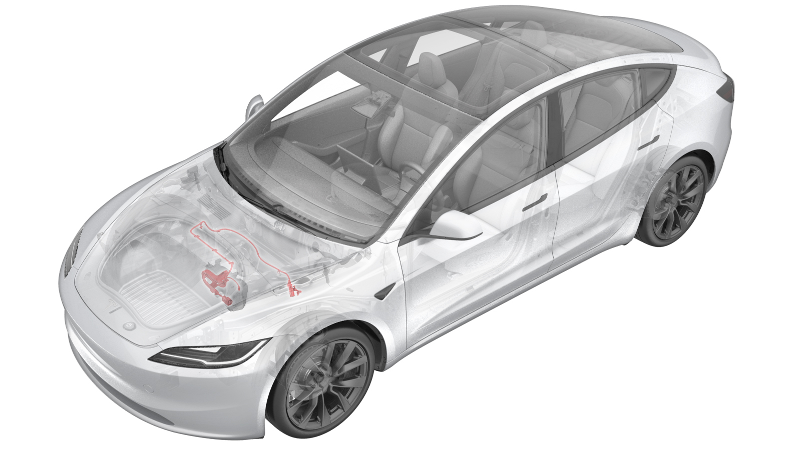
HV Harness - A/C Compressor (Remove and Replace)
 Correction code
4450010072
FRT
0.72
NOTE: Unless otherwise explicitly stated in the procedure, the correction code and FRT listed above reflect all of the work required to perform this procedure, including the linked procedures. Do not stack correction codes unless explicitly told to do so.
NOTE: See Flat Rate Times to learn more about FRTs and how they are created.
NOTE: See Personal Protection to make sure you
are wearing proper PPE when performing the procedure below.
NOTE: See Ergonomic Precautions for safe and healthy working practices.
Correction code
4450010072
FRT
0.72
NOTE: Unless otherwise explicitly stated in the procedure, the correction code and FRT listed above reflect all of the work required to perform this procedure, including the linked procedures. Do not stack correction codes unless explicitly told to do so.
NOTE: See Flat Rate Times to learn more about FRTs and how they are created.
NOTE: See Personal Protection to make sure you
are wearing proper PPE when performing the procedure below.
NOTE: See Ergonomic Precautions for safe and healthy working practices.
- 2024-05-08: Added steps of reworking the new A/C compressor HV harness.
High Voltage Awareness Care Pointsfor additional safety information.
Torque Specifications
| Description | Torque Value | Recommended Tools | Reuse/Replace | Notes |
|---|---|---|---|---|
| Bolt that attaches the HV harness bracket to the A/C compressor |
 9 Nm (6.6 lbs-ft) |
|
Reuse |
Remove
-
Place the vehicle on the 2-post
lift.
TIpEnsure the vehicle is not charging.
- Open all doors and lower all windows.
- Move both front seats forward.
- Remove the underhood storage unit. See Underhood Storage Unit (Remove and Replace).
- Perform the Vehicle HV Disablement Procedure. See Vehicle HV Disablement Procedure (Test/Adjust).
- Remove the front aero shield panel. See Panel - Aero Shield - Front (Remove and Replace).
-
Release the HV connector bracket from
the stud on the LH side of the firewall.
WarningThe video(s) included in this procedure are meant as an overview for supplemental purposes only. Follow all of the steps listed in the procedure to avoid damage to components and/or personal injury.
-
Pull the red locking tab away from the
connector body, press down on the yellow locking tab and pull the connector backward,
then press down on the green locking tab to disconnect the connector.
-
Release the clips (x2) that attach the
A/C compressor harness to studs on the RH side of the firewall.
- Lower the vehicle to a comfortable working height.
- Remove the fresh intake duct. See Fresh Air Intake - HVAC (Remove and Replace).
-
Use a clip prytool to release the
retaining clips (x4) that attach the A/C compressor HV harness to the shock tower
support brace.
NotePull upward on the clip to assist with removal. Do not pull upward on the HV cable.WarningThe video(s) included in this procedure are meant as an overview for supplemental purposes only. Follow all of the steps listed in the procedure to avoid damage to components and/or personal injury.
-
Release the connector locking tab, and
then disconnect the HVIL connector near the LH front strut tower.
NoteDO NOT push down on the red locking tab. Pull the tab away from the connector until the connector is unlocked, and then continue pulling to release the connector.TIpUse of the following tool(s) is recommended:
- Pick Miniature Soft Grip, 90 degree tip, 6 in
-
Release the connector locking tab,
then disconnect the A/C logic electrical connector from the A/C compressor.
NoteDO NOT push down on the red locking tab. Pull the tab away from the connector until the connector is unlocked, and then continue pulling to release the connector.TIpUse of the following tool(s) is recommended:
- Pick Miniature Soft Grip, 90 degree tip, 6 in
-
Use a clip prytool to release the
retaining clip that attaches the A/C compressor logic harness to the A/C compressor HV
harness bracket.
-
Disconnect the HV harness electrical connector from the A/C compressor.
TIpUse of the following tool(s) is recommended:
- Pick Miniature Soft Grip, 90 degree tip, 6 in
-
Remove the bolt that attaches the HV
harness bracket to the A/C compressor.
TIpUse of the following tool(s) is recommended:
- 13 mm 12-point deep socket
- Cordless Ratchet/Impact Driver
- Ratchet/torque wrench (for installation only)
-
Remove the A/C compressor HV harness.
Install
-
Check the new A/C compressor HV harness and the bracket. If the harness has a fir
free clip on its branch but the bracket has no hole for it, rework the HV harness HVIL
branch as following:
-
Install the A/C compressor harness.
NoteEnsure the HV harness bracket engages the upper bracket mount on the A/C compressor.
-
Install the clips (x4) that attach the
A/C compressor HV harness to the strut tower support brace.
-
Connect the HVIL connector near the LH
front strut tower, and then engage the locking tab.
NotePush the red locking tab into the connector to engage the locking mechanism. DO NOT push down or pull up on the red locking tab.
-
Clean the bracket, and then install the fir free clip or the adhesive clip to the
bracket.
-
Install the bolt that attaches the HV
harness bracket to the A/C compressor.9 Nm (6.6 lbs-ft)TIpUse of the following tool(s) is recommended:
- 13 mm 12-point deep socket
- Cordless Ratchet/Impact Driver
- Ratchet/torque wrench (for installation only)
-
Connect the HV harness electrical connector to the A/C compressor.
-
Install the retaining clip that
attaches the A/C compressor logic harness to the A/C compressor HV harness
bracket.
-
Connect the A/C compressor logic
electrical connector to the A/C compressor, and then engage the locking tab.
NotePush the red locking tab into the connector to engage the locking mechanism. DO NOT push down or pull up on the red locking tab.
-
Raise the vehicle to a comfortable
working height, and lower the lift onto locks.
CAUTION
Make sure there is an audible click of the locks on both sides before lowering, otherwise the vehicle may tilt to one side.
Make sure that the doors are clear of surrounding objects.
-
Install the clips (x2) that attach the
A/C compressor harness to the studs on the RH side of the firewall.
-
Push the red locking tab toward the
connector body to fully lock the connector.
-
Install the HV connector bracket to
the stud on the LH side of the firewall.
- Install the front aero shield panel. See Panel - Aero Shield - Front (Remove and Replace).
- Install the 2nd row lower seat cushion. See Seat Cushion - 2nd Row (Remove and Replace).
- Connect the LV power. See LV Power (Disconnect and Connect).
- Install the fresh intake duct. See Fresh Air Intake - HVAC (Remove and Replace).
- Install the underhood storage unit. See Underhood Storage Unit (Remove and Replace).
- Move both front seats to original position.
- Raise all windows and close all doors.
- Remove the lift arms from below the vehicle.