2025-11-25
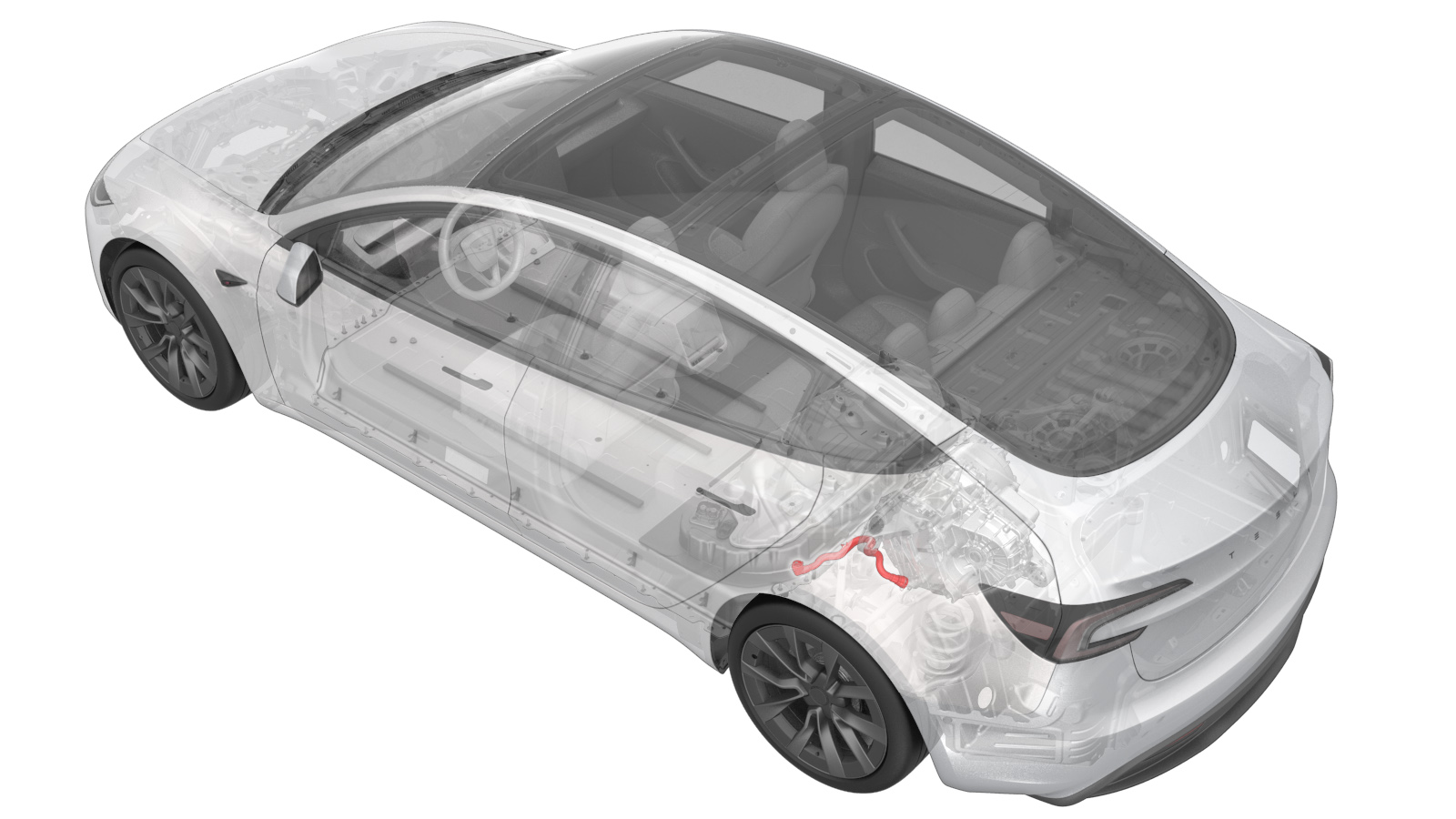
Hose - Inlet - Rear Drive Unit Inverter (Remove and Replace)
 Correction code
1830020032
FRT
0.42
NOTE: Unless otherwise explicitly stated in the procedure, the correction code and FRT listed above reflect all of the work required to perform this procedure, including the linked procedures. Do not stack correction codes unless explicitly told to do so.
NOTE: See Flat Rate Times to learn more about FRTs and how they are created.
NOTE: See Personal Protection to make sure you
are wearing proper PPE when performing the procedure below.
NOTE: See Ergonomic Precautions for safe and healthy working practices.
Correction code
1830020032
FRT
0.42
NOTE: Unless otherwise explicitly stated in the procedure, the correction code and FRT listed above reflect all of the work required to perform this procedure, including the linked procedures. Do not stack correction codes unless explicitly told to do so.
NOTE: See Flat Rate Times to learn more about FRTs and how they are created.
NOTE: See Personal Protection to make sure you
are wearing proper PPE when performing the procedure below.
NOTE: See Ergonomic Precautions for safe and healthy working practices.
Remove
- Raise and support the vehicle. See Raise Vehicle - 2 Post Lift.
- Remove the rear underhood apron. See Underhood Apron - Rear (Remove and Replace).
- Disconnect the LV power. See LV Power (Disconnect and Connect).
- Remove the rear aero shield panel. See Panel - Aero Shield - Rear (Remove and Replace).
- Remove the rear skid plate. See Skid Plate - HV Battery - Rear (Remove and Replace).
- Position a coolant drain container underneath the LH rear of the HV battery.
-
Release the clip, disconnect the rear
drive unit inverter inlet hose from the HV battery, and then immediately plug both
fittings.
-
Release the clip, disconnect the rear
drive unit inverter inlet hose from the rear drive unit inverter, and then immediately
plug both fittings.
-
Release the clip that attaches the
rear drive unit inverter inlet hose to the rear drive unit HV harness.
-
Remove the rear drive unit inverter
inlet hose down and out from between the rear subframe and the HV battery.
Install
-
Install the rear drive unit inverter
inlet hose in and up between the rear subframe and the HV battery.
-
Fasten the clip that attaches the rear
drive unit inverter inlet hose to rear drive unit HV harness.
-
Remove the plugs from the fittings,
immediately connect the rear drive unit inverter inlet hose to the rear drive unit
inverter, fasten the clip, and then perform a Push-Pull-Push check of the fitting.
-
Remove the plugs from the fittings,
immediately connect the rear drive unit inverter inlet hose to the HV battery, fasten
the clip, and then perform a Push-Pull-Push check of the fitting.
- Remove the coolant drain collector from under the vehicle.
- Install the HV battery rear skid plate. See Skid Plate - HV Battery - Rear (Remove and Replace).
- Install the rear shield panel. See Panel - Aero Shield - Rear (Remove and Replace).
- Connect LV power. See LV Power (Disconnect and Connect).
-
Remove the coolant bottle cap, and
then fill the coolant to the proper level.
NoteEnsure that the coolant level is at the "Max" line.
- Connect the vehicle to a laptop with Toolbox. See Toolbox (Connect and Disconnect).
-
In Toolbox, click Actions/Autodiag, type
"Purge" into the search field, click TEST_VCFRONT_X_THERMAL-COOLANT-AIR-PURGE, click Run, and allow the routine
to complete.
NoteMake sure vehicle is not in Drive, shifting the vehicle into Drive will stop this routine. The test will last approximately 10 mins. The test will vary speeds from 3500-6500 RPM (idle speed = ~1500 RPM) and actuate the valve between series and parallel. If speed hovers at 7000 RPM, it indicates the pump is air locked, perform the vacuum fill again. Continue to add coolant and purge until the coolant level reaches between the NOM and MAX Lines on the bottle.
-
Inspect the coolant level and top off
as necessary, and then install the coolant bottle cap.
NoteEnsure that the coolant level is at the "Max" line.
- Install the rear underhood apron. See Underhood Apron - Rear (Remove and Replace).
- Remove the vehicle from the 2 post lift. See Raise Vehicle - 2 Post Lift.