PCS2 Lite - Ancillary Bay (Remove and Install)
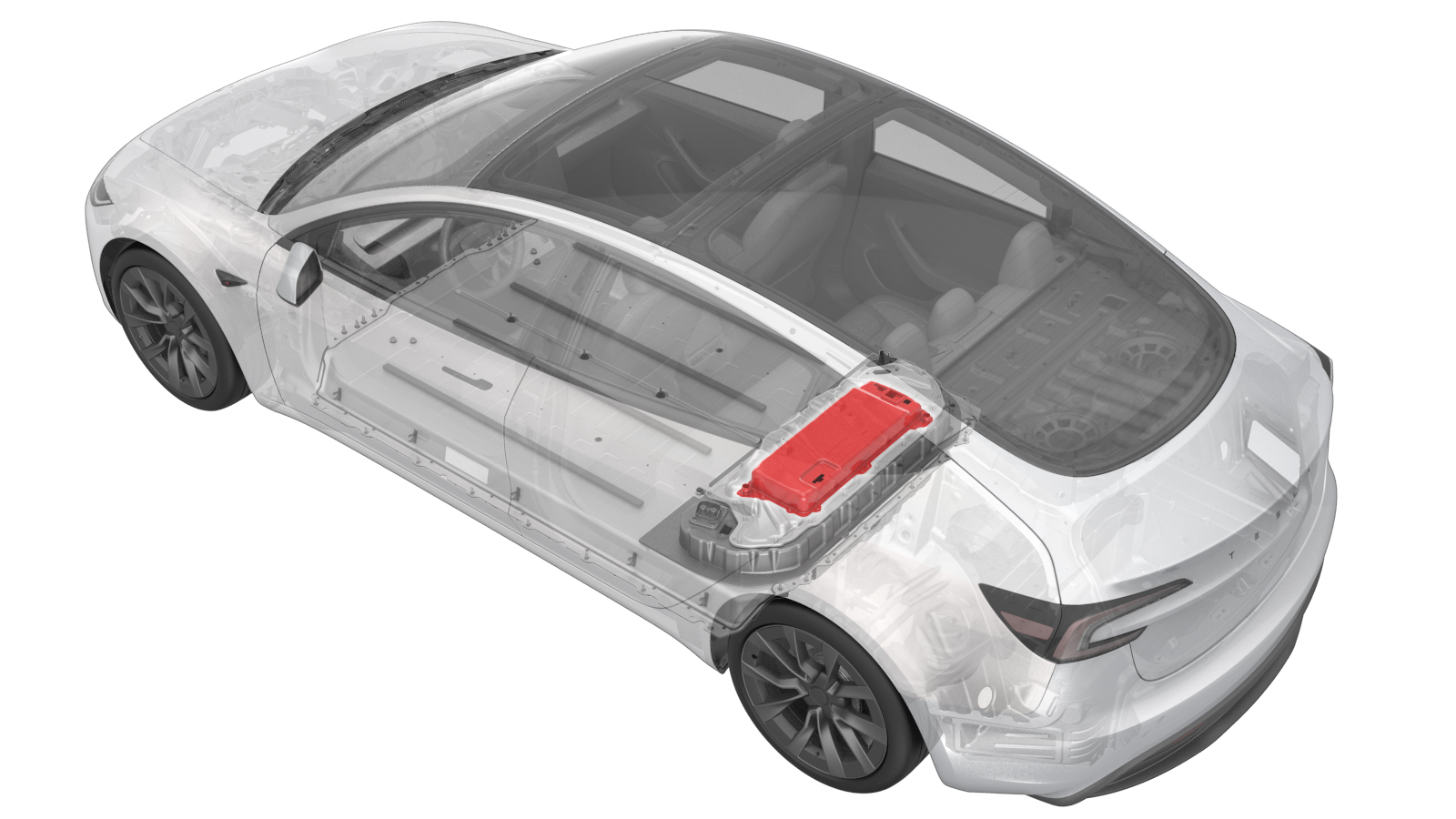 Correction code
16300500401
FRT
2.16
NOTE: Unless
otherwise explicitly stated in the procedure, the correction code and its
associated FRT reflect all of the work required to perform this procedure,
including the linked procedures. Do not stack correction
codes unless explicitly told to do so.
NOTE: See Flat Rate Times to
learn more about FRTs and how they are created.
NOTE: See Personal Protection to make
sure you are wearing proper PPE when performing the procedure below.
NOTE: See Ergonomic Precautions for safe and healthy
working practices.
Correction code
16300500401
FRT
2.16
NOTE: Unless
otherwise explicitly stated in the procedure, the correction code and its
associated FRT reflect all of the work required to perform this procedure,
including the linked procedures. Do not stack correction
codes unless explicitly told to do so.
NOTE: See Flat Rate Times to
learn more about FRTs and how they are created.
NOTE: See Personal Protection to make
sure you are wearing proper PPE when performing the procedure below.
NOTE: See Ergonomic Precautions for safe and healthy
working practices.
Torque Specifications
| Description | Torque Value | Recommended Tools | Reuse/Replace | Notes |
|---|---|---|---|---|
| Bolts (x5) that attach the PCS2 Lite to the HV battery |
 15 Nm (11.1 lbs-ft) - 180 degrees 15 Nm (11.1 lbs-ft) |
|
Replace | 1115833-00-B |
Remove
- Raise and support the vehicle. See Raise Vehicle - 2 Post Lift.
- Open all four doors and lower all four windows.
- Move the front seats forward.
-
Start the thermal fill/drain
routine.
- Disconnect the LV power. See LV Power (Disconnect and Connect) (Modify).
- Remove the rear skid plate. See Skid Plate - HV Battery - Rear (Remove and Replace).
- Perform the vehicle HV disablement procedure. See Vehicle HV Disablement Procedure (Test/Adjust).
-
Position coolant drain container
underneath LH rear of HV battery.
-
Disconnect the rear drive unit
inverter inlet tube from LH rear of HV battery.
NotePlug hose connections as needed. Coolant loss greater than 1 L will require a vacuum fill.
-
Attach the coolant drain hose adapter
to PCS outlet hose coupling.
NoteUse adapter with 90 degree angle. Make sure the locking tab is fully seated and the valve is open.
-
Connect the waste coolant container
hose to the drain and fill adaptor.
NotePush until an audible click is heard, then perform a push-pull-push test to verify the connection is fully seated.
-
Position the coolant drain container
underneath RH rear of vehicle.
-
Disconnect rear powertrain supply hose
from PCS inlet hose coupling.
Note1x spring clip. Plug hose connections as needed. Coolant loss greater than 1 L will require vacuum fill.
-
Connect the coolant leak test adapter
to the PCS inlet hose coupling.
NoteRemove the rubber plug from the coupler if installed. Make sure the locking clip is fully seated.
-
Connect the coolant leak test fixture
outlet hose to leak test adapter.
-
Connect the outlet hose to the leak
test fixture tool.
-
Close both valves on the coolant leak
test fixture tool.
-
Connect compressed air to coolant leak
test fixture tool.
NoteAir supply source should be above 50 psi.
-
Turn the inlet valve on leak test
fixture tool clockwise to open it, turn on the digital gauge and set to "psi", and then
adjust the regulator to 50 psi.
NoteTurn the regulator knob clockwise to increase pressure and counterclockwise to decrease pressure.CAUTIONUse caution as coolant may spill. Make sure to wear safety glasses.
- Set the timer to 2 minutes.
-
Slowly open the outlet valve on the
leak test fixture tool until the valve knob is inline with the airline.
CAUTIONUse caution as coolant may spill. Make sure to wear safety glasses.
- Start the 2-minute timer. Once the timer is complete, select Stop Reset.
- Close both valves on the coolant leak test fixture tool.
-
Disconnect the coolant leak test
adapter with hose from the PCS inlet hose coupling, and disconnect the coolant drain and
fill adapter with hose from the PCS outlet hose coupling.
-
Attach coolant leak test adapter with
hose to PCS outlet hose coupling.
Note1x spring clip. Make sure the locking tab is fully seated.
-
Attach coolant drain and fill adapter
with extension hose to PCS inlet hose coupling.
Note1x spring clip. Make sure the locking tab is fully seated.
- Repeat step 19 to step 23.
-
Disconnect compressed air from the
leak test fixture tool.
-
Disconnect waste coolant container
from the drain and fill adapter.
-
Disconnect coolant drain and fill
adapter from the PCS inlet hose coupling.
NoteInstall plug to inlet hose coupling. If the battery is returned to Reman, remove the special tool plugs.
-
Disconnect the coolant leak test
fixture outlet hose from the leak test adapter.
-
Disconnect the coolant leak test
adapter from the PCS outlet hose coupling.
Note1x spring clip
- Lower the vehicle until tires are touching the ground
- Remove the 2nd row seat cushion and disconnect the harness connectors. See Seat Cushion - 2nd Row (Remove and Replace).
- Remove the ancillary bay cover. See Ancillary Bay Cover (Remove and Install).
- Remove the pyrotechnic battery disconnect. See Pyro Disconnect - HV Battery (Remove and Replace).
-
Use the rubber bands to secure the
high voltage controller (HVC) to the body.
-
Place absorbent sheets below and
around the PCS2 Lite coolant inlet and outlet hoses to prevent excess coolant from
dripping.
-
Disconnect the PCS2 Lite coolant inlet
hose from the PCS2 Lite by releasing the clips (x2) with the PCS Coolant Connector
Removal Tool (1111868-00-B). Place an absorbent sheet under the hose to catch excess
coolant, visually inspect for coolant residue and clean with a shop towel if needed.
Install two plugs on the PCS2 Lite and hose, and discard the O-ring.
-
Disconnect the PCS2 Lite coolant
outlet hose from the PCS2 Lite by releasing the clips (x2) with the PCS Coolant
Connector Removal Tool (1111868-00-B). Place an absorbent sheet under the hose to catch
excess coolant, visually inspect for coolant residue and clean with a shop towel if
needed. Install two plugs on the PCS2 Lite and hose, and discard the O-ring.
-
Disconnect the AC filter
harness connector from the PCS2 Lite.
-
Disconnect the HV DC harness connector
from the PCS2 Lite by pulling the locking tab upward.
-
Disconnect the PCS2 Lite logic
connector from the PCS2 Lite.
-
Disconnect the PCS2 Lite LV connector
from the PCS2 Lite.
-
Remove and discard the bolts (x5) that
attach the PCS2 Lite to the HV battery.
NoteEnsure only the 8mm fasteners are removed; do not remove the T20 fasteners.TipUse of the following tool(s) is recommended:
- Skt, 1/4" Sq Dr, 8mm, HV Insulated
-
Secure suction cups to the PCS2 Lite
by pressing the plunger continuously until the red line is no longer visible.
-
Lift the PCS2 Lite up and remove it
from the ancillary bay by releasing the datums (x2) and slightly tilting the rear
upward.
NoteInspect for missing insulators underneath and install any if needed, then visually check for coolant residue and clean with a shop towel if necessary.
Install
-
Align the datums (x2) into the PCS2 Lite holes, slightly tilt the rear upward and
lower it into the ancillary bay.
NoteEnsure that all busbar insulators beneath PCS2 Lite are present.
-
Remove suction cups from the PCS2
Lite.
-
Install new bolts (x5) that attach the
PCS2 Lite to the HV battery.15 Nm (11.1 lbs-ft) - 180 degrees15 Nm (11.1 lbs-ft)TipUse of the following tool(s) is recommended:
- Skt, 1/4" Sq Dr, 8mm, HV Insulated
NoteTighten the bolt to 15 Nm, back off 180 degrees, then torque to 15 Nm. -
Connect the AC filter harness connector to the PCS2 Lite by pushing it downward, then
pressing the locking tab down to secure it.
-
Connect the PCS2 Lite LV connector to the PCS2 Lite by pushing it downward, then
pressing the locking tab down to secure it.
-
Connect the PCS2 Lite logic connector
to the PCS2 Lite.
-
Connect the HV DC harness connector to
the PCS2 Lite by pushing it downward, then pressing the locking tab down to secure
it.
-
Connect the PCS2 Lite coolant inlet hose to the PCS2 Lite as follows:
- Remove 2 plugs from the coupling and hose.
- Place an absorbent sheet under the hose to catch excess coolant.
- Apply a light amount of Krytox 203 to install a new O-ring (1803223-00-A).
- Align the hose to the coupling and secure the clips (x2); use caution not to damage the O-ring.
- Perform a push-pull-push test to ensure the coolant hose is fully latched, then visually verify the clips are fully seated.
-
Connect the PCS2 Lite coolant outlet hose to the PCS2 Lite as follows:
- Remove 2 plugs from the coupling and hose.
- Place an absorbent sheet under the hose to catch excess coolant.
- Apply a light amount of Krytox 203 to install a new O-ring (1803223-00-A).
- Align the hose to the coupling and secure the clips (x2); use caution not to damage the O-ring.
- Perform a push-pull-push test to ensure the coolant hose is fully latched, then visually verify the clips are fully seated.
-
Release the bungee cords and position
the HVC onto the PCS2 Lite.
- Install the pyrotechnic battery disconnect. See Pyro Disconnect - HV Battery (Remove and Replace).
-
Remove the HVC logic cap.
- Install the ancillary bay cover. See Ancillary Bay Cover (Remove and Replace).
-
Connect the coolant leak test adapter
plug to the PCS outlet hose coupling.
NoteRemove the rubber plug from PCS outlet hose coupling if present. Install 90 degree leak test adapter with NPT plug. Make sure the locking clip is fully seated.
-
Connect the coolant leak test adapter
to the PCS inlet hose coupling.
NoteRemove the rubber plug from PCS outlet hose coupling if present. Make sure the locking clip is fully seated.
-
Connect the coolant leak test fixture
outlet hose to leak test adapter.
-
Connect the outlet hose to the leak
test fixture tool.
-
Close both valves on the coolant leak
test fixture tool.
-
Connect compressed air to coolant leak
test fixture tool.
NoteAir supply source should be above 50 psi.
-
Turn the inlet valve on leak test
fixture tool clockwise to open it, turn on the digital gauge and set to "psi", and then
adjust the regulator to 50 psi.
NoteTurn the regulator knob clockwise to increase pressure and counterclockwise to decrease pressure.CAUTIONUse caution as coolant may spill. Make sure to wear safety glasses.
-
Slowly open the outlet valve on the
leak test fixture tool until the valve knob is inline with the airline.
CAUTIONUse caution as coolant may spill. Make sure to wear safety glasses.
-
Allow the pressure in the PCS coolant
loop to stabilize at 50 psi.
- Allow 110 seconds for the pressure to stabilize.
- Close the inlet valve on the coolant leak test fixture tool.
- Record the PCS coolant loop leak check starting pressure.
-
Allow 240 seconds to test and then record the ending pressure value. The max delta
between the start and end pressures is 0.5 psi.
NoteIf the difference is greater than 0.5 psi, check the hose, adapter, and plug fittings, check the regulator pressure, then retest. If the difference is still greater than 0.5 psi, escalate a Toolbox session.
-
Disconnect compressed air from the
leak test fixture tool.
- Slowly open the inlet valve on the leak test fixture tool to discharge air from coolant system.
-
Disconnect the coolant leak test
fixture hose from the leak test adapter.
-
Disconnect the coolant leak test
adapter from the PCS inlet hose coupling.
-
Position the coolant drain container
underneath RH rear of vehicle.
-
Connect the rear powertrain supply
hose to the PCS inlet hose coupling.
Note
- Remove plugs and perform push-pull-push test to make sure hose is fully engaged.
- Coolant loss greater than 1 L will require vacuum fill.
-
Disconnect the coolant leak test
adapter plug from the PCS outlet hose coupling.
-
Position coolant drain container
underneath LH rear of the vehicle.
-
Connect the RDU inverter inlet tube to
PCS outlet hose coupling.
Note
- Remove plugs and perform push-pull-push test to make sure hose is fully engaged.
- Coolant loss greater than 1 L will require vacuum fill.
- Remove the coolant drain container from underneath vehicle.
- Install the rear skid plate. See Skid Plate - HV Battery - Rear (Remove and Replace).
- Perform a vacuum refill of the cooling system. See Cooling System - Vacuum Refill (Test/Adjust).
- Exit the Service Mode. See .
- Install the rear underhood apron. See Underhood Apron - Rear (Remove and Replace).
- Raise all windows and close all doors.
- Remove the vehicle from the lift.