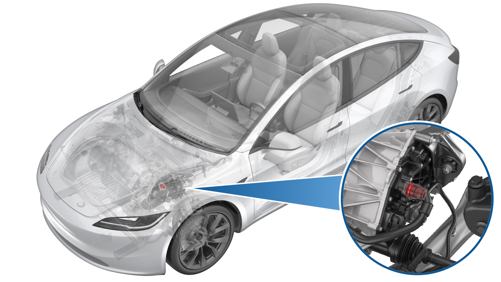
Fluid Coupling (Straight) - Front Drive Inverter (Remove and Replace)
 Correction code
3920010042
FRT
0.54
NOTE: Unless otherwise explicitly stated in the procedure, the correction code and FRT listed above reflect all of the work required to perform this procedure, including the linked procedures. Do not stack correction codes unless explicitly told to do so.
NOTE: See Flat Rate Times to learn more about FRTs and how they are created.
NOTE: See Personal Protection to make sure you
are wearing proper PPE when performing the procedure below.
NOTE: See Ergonomic Precautions for safe and healthy working practices.
Correction code
3920010042
FRT
0.54
NOTE: Unless otherwise explicitly stated in the procedure, the correction code and FRT listed above reflect all of the work required to perform this procedure, including the linked procedures. Do not stack correction codes unless explicitly told to do so.
NOTE: See Flat Rate Times to learn more about FRTs and how they are created.
NOTE: See Personal Protection to make sure you
are wearing proper PPE when performing the procedure below.
NOTE: See Ergonomic Precautions for safe and healthy working practices.
Equipment:
- 1135762-00-A Kit, Svc Plug, Cooling Hose, Model 3
- 1080568-00-A Fluid Catcher
- 1060071-00-A Torque Wrench ¼ in Dr Hexagon
- 1065131-00-A Kit, Battery Coolant Drain
| Description | Torque Value | Recommended Tools | Reuse/Replace | Notes |
|---|---|---|---|---|
| Bolt that attaches the straight fluid coupling and the front drive unit inverter |
 6 Nm (4.4 lbs-ft) |
|
Reuse |
Remove
- Raise and support the vehicle. See Raise Vehicle - 2 Post Lift.
- Open all doors and lower all windows.
- Unlock the vehicle gateway. See Gateway Unlock.
-
On the touchscreen, tap the Service Mode "wrench" (at the bottom of the
touchscreen UI), and then tap , and then allow the routine to complete.
TIpThe routine has a 5-hour time limit.
- Disconnect the LV battery power. See LV Power (Disconnect and Connect).
-
Release the clips (x3) to remove the fresh air gutter assembly.
- Remove the front aero shield panel. See Panel - Aero Shield - Front (Remove and Replace).
- Position the coolant drain container under the LH front of the front drive unit.
-
Disconnect the front drive unit inverter inlet hose from the fluid
coupling, and plug the ends of both fittings as soon as possible to avoid
coolant loss.
TIpCoolant loss greater than 1L requires vacuum fill.
-
Remove the bolt that attaches the straight fluid coupling and the front
drive unit inverter, and then remove and discard the straight fluid
coupling.
TIpUse of the following tool(s) is recommended:
- Cordless drill
- Torx T25 Bit
- Torx T25 socket
- Flex head ratchet/flex head torque wrench
- Ratchet/torque wrench
Install
-
Install the bolt that attaches the straight fluid coupling and the front
drive unit inverter.6 Nm (4.4 lbs-ft)TIpUse of the following tool(s) is recommended:
- Cordless drill
- Torx T25 Bit
- Torx T25 socket
- Flex head ratchet/flex head torque wrench
- Ratchet/torque wrench
-
Remove the plugs on the ends of fittings, and then connect the front drive
unit inverter inlet hose to the fluid coupling.
TIp
Coolant loss greater than 1L requires vacuum fill.
Perform a push-pull-push test to make sure that the hose is fully secured.
- Remove the coolant drain container from underneath the vehicle.
- Install the front aero shield panel. See Panel - Aero Shield - Front (Remove and Replace).
-
Perform a coolant pressure
test:
- Connect the LV battery power. See LV Power (Disconnect and Connect).
- Unlock the vehicle gateway. See Gateway Unlock.
- On the touchscreen, tap the Service Mode "wrench" (at the bottom of the touchscreen UI), and then tap , and then allow the routine to complete.
-
On the touchscreen, tap the Service Mode "wrench" (at the bottom of the
touchscreen UI), and then tap , and then allow the routine to complete.
TIp
- The routine will last for a while after the stop message displays. The coolant pumps are audible.
- The test lasts for approximately 10 mins. Do not start another routine during this time.
- Make sure that the vehicle is not in Drive. Putting the vehicle into Drive will stop this routine.
- The speed in the test varies from 3500-6500 RPM (idle speed = ~1500 RPM) and the actuated valve varies between SERIES and PARALLEL.
- If the speed hovers at 7000 RPM, it indicates the pumps are air locked. Perform the vacuum fill again. Continue to add the coolant and purge until the coolant level reaches between the NOM and MAX Lines on the bottle.
-
Inspect the coolant level,
top off as necessary, and then install the coolant bottle cap.
TIpEnsure that the coolant level is at the "Max" line.
- On the touchscreen, tap the Service Mode "wrench" (at the bottom of the touchscreen UI), and then tap , tap the START button next to Test Thermal Performance, click Run, and then allow the routine to complete.
-
Secure the clips (x3) to install the fresh air gutter assembly.
- Install the rear underhood apron. See Underhood Apron - Rear (Remove and Replace).
- Disable Service Mode. See Service Mode.
- Raise all windows and close all doors.
- Remove the lift arms from below the vehicle.