Steering Gear (LHD) (Remove and Install)
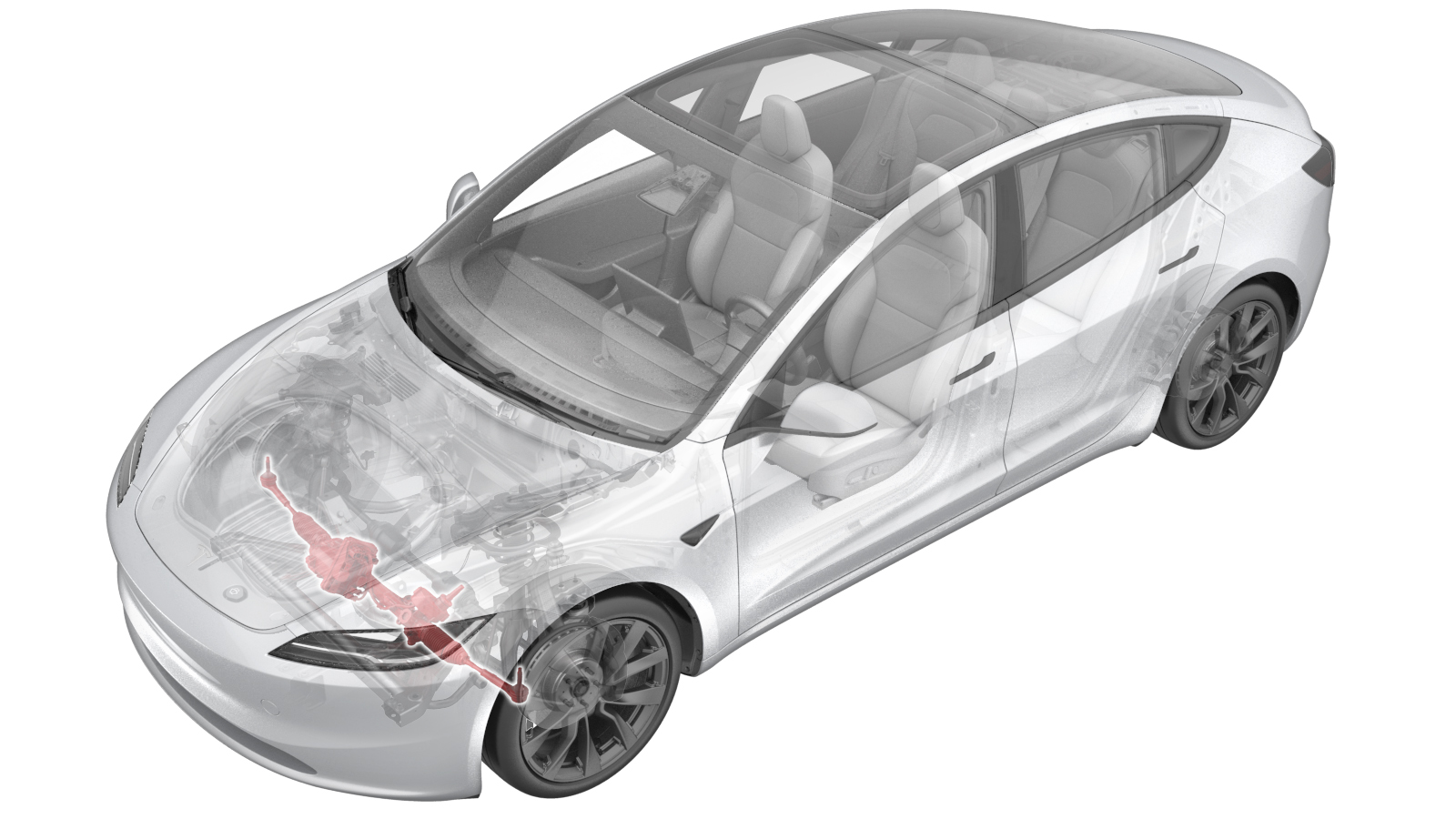 Correction code
3201010011
FRT
1.50
NOTE: Unless
otherwise explicitly stated in the procedure, the correction code and its
associated FRT reflect all of the work required to perform this procedure,
including the linked procedures. Do not stack correction
codes unless explicitly told to do so.
NOTE: See Flat Rate Times to
learn more about FRTs and how they are created.
NOTE: See Personal Protection to make
sure you are wearing proper PPE when performing the procedure below.
NOTE: See Ergonomic Precautions for safe and healthy
working practices.
Correction code
3201010011
FRT
1.50
NOTE: Unless
otherwise explicitly stated in the procedure, the correction code and its
associated FRT reflect all of the work required to perform this procedure,
including the linked procedures. Do not stack correction
codes unless explicitly told to do so.
NOTE: See Flat Rate Times to
learn more about FRTs and how they are created.
NOTE: See Personal Protection to make
sure you are wearing proper PPE when performing the procedure below.
NOTE: See Ergonomic Precautions for safe and healthy
working practices.
Equipment:
- 1090880-00-A Steering Wheel Holder **Std. w/ Hunter Alignment Equip.**
- 1065131-00-A Kit, Battery Coolant Drain
- 1773595-00-A RJ45 Ethernet Cable
- 1090881-00-A Brake Pedal Depressor
- 1044206-00-A Wheel Trim Removal Tool
- 1049463-00-A Steering Wheel Level
- 1773092-00-A Diagnostic Harness Adapter - All Models
Torque Specifications
| Description | Torque Value | Recommended Tools | Reuse/Replace | Notes |
|---|---|---|---|---|
| Bolt that attaches the steering gear assembly to the electric steering column |
 18 Nm (13.3 lbs-ft) |
|
Replace | 1111523-00-A |
| Jamb nut to the LH outer tie rod end |
80 Nm (59.0 lbs-ft) |
|
Reuse | |
| Nuts that attach the LH and the RH front tie rod ends to the LH and the RH front suspension knuckles |
180 Nm (132.7 lbs-ft) |
|
Replace | 1109263-00-B |
| Outer bolts that attach the steering gear assembly to the front subframe |
47 Nm (34.7 lbs-ft) |
|
Reuse | |
| Inner bolts (x2) that attach the steering gear assembly to the front subframe |
75 Nm (55.3 lbs-ft) |
|
Reuse | |
| LH and RH bolts (x2) that attach the bottom of the condenser fan module to the ankle catcher |
10 Nm (7.4 lbs-ft) |
|
Reuse | |
| Bolts (x2) that attach the underhood storage unit reinforcement bracket to the cooling fan |
16 Nm (11.8 lbs-ft) |
|
Reuse |
Remove
- Raise and support the vehicle. See Raise Vehicle - 2 Post Lift.
- Disconnect the LV power. See LV Power (Disconnect and Connect) (Modify).
- Remove the underhood storage unit. See Underhood Storage Unit (Remove and Replace).
-
Remove the harness clips (x3) from the
underhood storage unit reinforcement assembly.
-
Remove the bolts (x2) that attach the
underhood storage unit reinforcement bracket to the cooling fan, and slide the underhood
storage unit reinforcement rearward to remove it from the cooling fan module
assembly.
TipUse of the following tool(s) is recommended:
- 10 mm socket
- Cordless Ratchet/Impact Driver
-
Remove the LH bolt that attaches the
bottom of the condenser fan module to the ankle catcher, then repeat this step on the RH
side.
NoteHold the condenser fan module to ease removal of the bolts.TipUse of the following tool(s) is recommended:
- 8 mm socket
- Cordless Ratchet/Impact Driver
Figure 1. LH shown, RH similar -
Position the cooling fan assembly away
from the steering gear, and use a bungee cord to lift the radiator away from the
steering gear to gain clearance for removal and installation.
- Remove the front wheels. See Wheel Assembly (Remove and Install).
-
Loosen the jamb nut that secures the
LH outer tie rod end.
TipUse of the following tool(s) is recommended:
- Combination wrench 12pt 21mm
-
Remove and discard the nuts (x2) that
attach the LH and the RH front tie rod ends to the LH and the RH front suspension
knuckles, and then remove the both tie rod ends from the knuckles.
TipUse of the following tool(s) is recommended:
- Cordless 1/2in Dr Impact
- 22 mm deep socket
- 1/2 in to 3/4 in adapter - 1717365-00-A
- Ratchet/torque wrench
-
Rotate the LH tie rod end
counter-clockwise to remove it from the steering gear assembly.
NoteRecord the number of turns during removal.
- Lower the vehicle partially and set the lift onto locks.
-
Turn the steering wheel to the
rightmost position, and lock the steering wheel into position.
-
Disconnect the steering gear assembly
connectors (x4).
-
Disconnect the connector and the clip
that attach the front drive unit front subframe harness to the vehicle.
-
Release the clip that secures the
radiator inlet hose to the vehicle.
-
Remove and discard the bolt that
attaches the steering gear assembly to the electric steering column.
TipUse of the following tool(s) is recommended:
- 13 mm socket
- Ratchet/torque wrench
-
Slide the electric steering column
upward to remove it from the steering gear assembly.
-
Remove the outer bolts (x2) that
attach the steering gear assembly to the front subframe.
TipUse of the following tool(s) is recommended:
- Flex head ratchet/flex head torque wrench
- 11 in extension
- 15 mm socket
-
Remove the inner bolts (x2) that
attach the steering gear assembly to the front subframe.
TipUse of the following tool(s) is recommended:
- Ratchet/torque wrench
- 6 in extension
- 18 mm socket
- 3 in extension
-
With assistance, slide the steering
rack assembly fully towards the RH side of the vehicle, and then remove it from the
vehicle.
CAUTIONBe careful around the AC lines and the superbottle.Note
Lift the LH inner tie rod up first, and then maneuver the rest of the rack outward, avoiding the AC lines and surrounding components.
Make sure the LH side of the coolant hose is below the LH inner rod to ease removal.
Install
-
Position the RH side of the steering
gear assembly into the underhood storage area, and then slide the LH side into the
vehicle. Position the steering rack so that the bolt holes are aligned.
-
Loosely install the inner bolts (x2)
that attach the steering gear assembly to the front subframe.
TipUse of the following tool(s) is recommended:
- Ratchet/torque wrench
- 6 in extension
- 18 mm socket
- 3 in extension
-
Loosely install the outer bolts (x2)
that attach the steering gear assembly to the front subframe.
TipUse of the following tool(s) is recommended:
- Flex head ratchet/flex head torque wrench
- 11 in extension
- 15 mm socket
-
Tighten the inner bolts that attach
the steering gear assembly to the front subframe.75 Nm (55.3 lbs-ft)TipUse of the following tool(s) is recommended:
- Ratchet/torque wrench
- 6 in extension
- 18 mm socket
- 3 in extension
-
Tighten the outer bolts that attach
the steering gear assembly to the front subframe.47 Nm (34.7 lbs-ft)TipUse of the following tool(s) is recommended:
- Flex head ratchet/flex head torque wrench
- 11 in extension
- 15 mm socket
-
Connect the steering gear assembly
connectors (x4).
-
Connect the clip and the connector
that attach the front drive unit front subframe harness to the vehicle.
-
Slide the electric steering column
downward to install it to the steering gear assembly.
-
Install the new bolt that attaches the
steering gear assembly to the electric steering column.18 Nm (13.3 lbs-ft)TipUse of the following tool(s) is recommended:
- 13 mm socket
- Ratchet/torque wrench
-
Install the clip that secures the
radiator inlet hose to the vehicle.
-
Release the radiator assembly and move
it back to the normal position.
- Install and hand-tighten the LH and RH bolts (x2) that attach the bottom of the condenser fan module to the ankle catcher.
-
Torque the bolts that attach the
bottom of the condenser fan module to the ankle catcher.10 Nm (7.4 lbs-ft)NoteUse of the following tool(s) is recommended:
- 8 mm socket
- Ratchet/torque wrench
-
Install the underhood storage unit
reinforcement assembly to the cooling fan assembly.
-
Install the bolts (x2) that attach the
underhood storage unit reinforcement bracket to the cooling fan, and slide the underhood
storage unit reinforcement rearward to remove it from the cooling fan module
assembly.16 Nm (11.8 lbs-ft)TipUse of the following tool(s) is recommended:
- 10 mm socket
- 4 in extension
- Cordless 1/4in Dr Ratchet
-
Install the harness clips (x3) to the
underhood storage unit reinforcement assembly.
- Connect the LV power. See LV Power (Disconnect and Connect) (Modify).
- Install the underhood storage unit. See Underhood Storage Unit (Remove and Replace).
- Remove the steering wheel holder and turn the steering wheel to the center position.
- Enable Service Mode. See Service Mode.
-
On the touchscreen, select
and inspect whether the steering wheel illustration is approximately at 0
degrees.
NoteIf the steering wheel is off by ±360 degrees, reinstall the steering column and steering gear assembly accordingly.
- Raise the vehicle fully and lower the lift onto locks.
-
Rotate the LH tie rod end clockwise
with the exact number of turns noted during removal to install it to the steering gear
assembly.
NoteAlign the LH front tie rod end to the original location marked on threads.
-
Install the new nuts (x2) that attach
the LH and the RH front tie rod ends to the LH and the RH front suspension knuckles to
install the both tie rod ends to the knuckles.180 Nm (132.7 lbs-ft)TipUse of the following tool(s) is recommended:
- Cordless 1/2in Dr Impact
- 22 mm deep socket
- 1/2 in to 3/4 in adapter - 1717365-00-A
- Ratchet/torque wrench
-
Tighten the jamb nut to the LH outer
tie rod end.80 Nm (59.0 lbs-ft)TipUse of the following tool(s) is recommended:
- Combination wrench 12pt 21mm
- Lower the vehicle partially and set the lift onto locks.
- Install the front wheels. See Wheel Assembly (Remove and Install).
- Exit the Service Mode. See Service Mode.
- Raise the LH front window and close the LH front door.
- Remove the lift arms from below the vehicle.
- Refer to the Alignment Requirement tables to determine whether an EPAS alignment check (EC) or four wheel alignment check (AC) is necessary. If performed, add the alignment check/adjust as a separate activity. See Alignment Requirement - Suspension.