2025-06-10
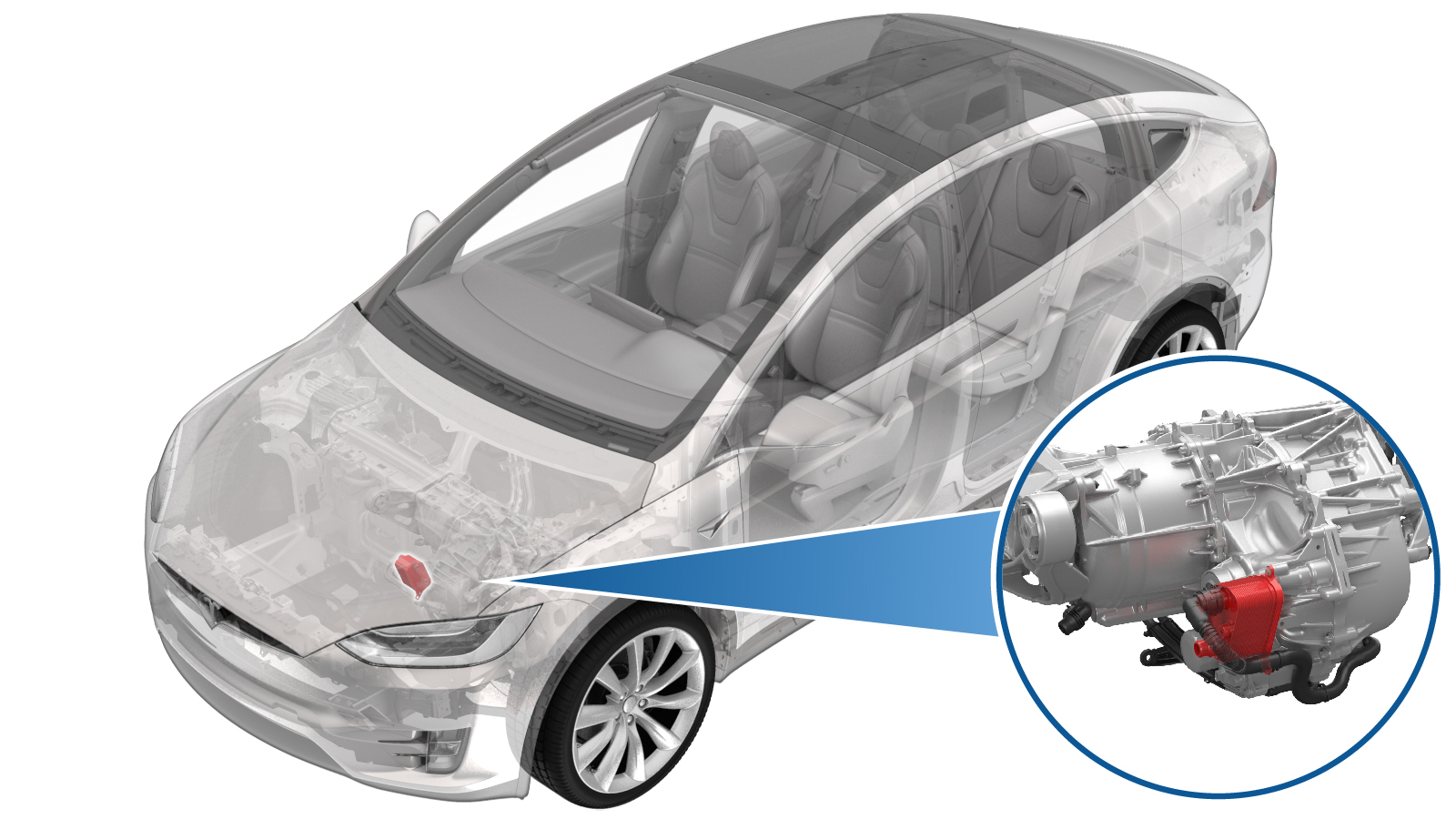
Heat Exchanger - Front Drive Unit (Remove and Install)
 Correction code
39308512
1.20
NOTE: Unless otherwise explicitly stated in the procedure, the correction code and FRT listed above reflect all of the work required to perform this procedure, including the linked procedures. Do not stack correction codes unless explicitly told to do so.
NOTE: See Flat Rate Times to learn more about FRTs and how they are created.
NOTE: See Personal Protection to make sure you
are wearing proper PPE when performing the procedure below.
NOTE: See Ergonomic Precautions for safe and healthy working practices.
Correction code
39308512
1.20
NOTE: Unless otherwise explicitly stated in the procedure, the correction code and FRT listed above reflect all of the work required to perform this procedure, including the linked procedures. Do not stack correction codes unless explicitly told to do so.
NOTE: See Flat Rate Times to learn more about FRTs and how they are created.
NOTE: See Personal Protection to make sure you
are wearing proper PPE when performing the procedure below.
NOTE: See Ergonomic Precautions for safe and healthy working practices.
- 2025-06-06: Updated procedure without compressor removal.
- 2025-01-28: Revised procedure and added references.
Removal
- Remove the underhood storage unit. See Underhood Storage Unit (Remove and Replace).
- Remove the HEPA filter. See Filter - HEPA (Remove and Replace).
- Disconnect 12V power. See Disconnect 12V Power.
-
Clamp the coolant hose.
-
Move coolant hose to create additional
clearance.
NoteUse a clip pry tool to remove the clip holding the coolant hose, then lower the hose to allow for additional clearance.
-
Remove the upper bolt that attaches
the heat exchanger to the FDU.
- Remove the front aero shield panel. See Panel - Aero Shield - Front (Remove and Replace).
-
Remove the bolts that attach the front
bash plate extrusion.
-
Remove and discard the bolts (x2) that
attach the front of the HV battery.
-
Remove and discard the front HV
battery bolts (x4).
-
Remove the bolts (x2) that attach the
skid plate to the front subframe.
-
Position an oil drain container under
the oil pump area.
-
Disconnect the front drive unit oil
pump connector.
-
Remove the bolts (x2) that attach the
oil pump to the FDU.
-
Remove the oil pump from the
FDU.
NotePry the pump away from the FDU with a pry tool or flat blade screwdriver. Make sure that the FDU casting is not damaged. Allow the oil to drain from the FDU.
-
Position a foldable funnel under the
FDU.
-
Remove the oil filter from the
FDU.
-
Remove foldable funnel
- Remove the oil drain container from under the vehicle.
-
Position coolant drain container under
the LH front corner of the vehicle to catch vehicle coolant
-
Release the FDU outlet hose from the
heat exchanger and plug the heat exchanger.
Note1x spring clip. Allow excess coolant to fully drain.
-
Release the upper coolant hose from
the heat exchanger and plug the heat exchanger.
Note1x spring clip. Allow excess coolant to fully drain.
-
Remove the fir tree clip from the heat
exchanger and move hose aside
-
Remove the lower bolt that attaches
the heat exchanger to the FDU.
-
Remove the heat exchanger from the FDU
assembly.
NoteSome oil will spill out of the FDU after removal
Installation
-
Inspect seals of the new heat
exchanger
NoteReplace any damaged seals. Lubricate with drive unit oil before installation
-
Position the heat exchanger onto the
FDU assembly.
-
Install the lower fastener securing
the heat exchanger to the FDU.
 5 Nm (3.7 lbs-ft) + 30degNote1x bolt, EP10, 5 Nm + 30 degrees
 -
Install the clip securing the upper
coolant hose to the heat exchanger
Note1x fir tree clip
-
Install the upper coolant hose onto
the heat exchanger .
Note1x spring clip. Perform a push-pull-push test.
-
Install the FDU outlet hose onto the
heat exchanger.
Note1x spring clip. Perform a push-pull-push test.
-
Install the clip that attaches the oil
pump harness pigtail to the heat exchanger.
- Remove the coolant drain container from under the LH front of the vehicle.
-
Position an oil drain container under
the oil pump area.
-
Remove the fill plug from the
FDU.
-
Inspect seals and o-rings
NoteInspect O-rings on removed parts, 3 O-rings on pump, one O-ring on fill plug. if missing O-ring on pump, ensure it is not left in housing. If damaged O-ring on plug, replace plug. Replace all O-rings on oil pump if damaged. Check seal on oil filter; if missing, check if still on housing and remove before installing.
-
Install the new oil filter.
NoteSpin clockwise, 3 Nm and 135 degrees. Lubricate seal prior to installation.
-
Install the oil pump into the
FDU
NoteUse residual oil in the oil pump cavity to lubricate the seals of the oil pump before installation, Align bolt holes with housing
-
Install the bolts (x2) that attach the
oil pump to the FDU.5 Nm (3.7 lbs-ft) + 20 deg
-
Set up fill kit.
NoteSet fluid level to 2000 ml in measuring container
-
Install fluid transfer pump
NoteTrim both input and output hoses to 26". Insert output hose into the fill hole until fully seated, then pull back 5 mm.
-
Set up the fill process.
NotePlace measured fluid container in drain basket, fully submerge input hose, prime pump with ATF fluid.
-
Connect the 12V power supply tool
connector to the oil pump.
-
Pump ATF fluid into the front drive
unit
NoteAssistant required. Pump 5 full strokes from the fluid container, then run the pump via the switch box for entire fill and keep running until drain plug installed. Do not run pump when dry. If pump is not running and drain plug not installed, fluid will drain from the plug within 10 seconds.
-
Install the fill plug into the
FDU.15 Nm (11.1 lbs-ft)
-
Disconnect the 12V power supply tool
from oil pump
Note1x electrical connector
-
Connect the front drive unit oil pump
connector
Note1x electrical connector
- Clean area with brake cleaner and wipe residual fluid off with a towel.
- Remove the oil drain container from under the vehicle.
-
Install the skid plate between the
battery pack and subframe.
-
Install the bolts (x2) to attach the
skid plate to the subframe.10 Nm (7.4 lbs-ft)
-
Install new patch bolts (x4) at the
front of the HV battery with battery powered drill
Note4x patch bolts, 30 Nm. Install new patch bolts, Do not over tighten bolts. Torque at a later step.
-
Torque the front bolts of the HV
battery to 30 Nm.
-
Install new 21mm bolts (x2) at the
front of HV battery with battery powered drill.
NoteDo not over tighten the bolts. Torque at a later step.
-
Torque the bolts (x2) that attach the
front of HV battery to the vehicle to 115 Nm.
-
Install the bolts (x2) that attach the
front bash plate extrusion.16 Nm (11.8 lbs-ft)
- Install the front aero shield. See Panel - Aero Shield - Front (Remove and Replace).
-
Install the upper fastener that
attaches the heat exchanger to the FDU.5 Nm (3.7 lbs-ft) + 30 deg
-
Install the clip to hold the coolant hose in place.
-
Remove the coolant hose clamp.
- Reconnect 12V power. See Disconnect 12V Power.
- Perform a coolant air purge. See Cooling System - Partial Refill and Bleed.
- Install the HEPA filter. See Filter - HEPA (Remove and Replace).
- Install the underhood storage unit. See Underhood Storage Unit (Remove and Replace).