2026-02-27
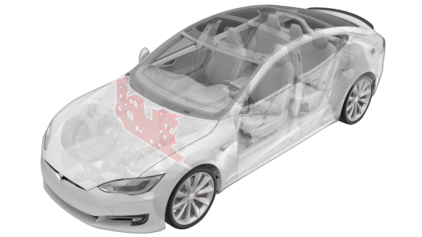
Insulator - Dash - Interior - RH (Remove & Replace)
 Correction code
15301202
Correction code
15301202
- 2025-01-14: Added note on separately adding correction code 18200102 for A/C refrigerant recovery and recharge.
Note
This procedure requires the A/C
Refrigerant (Recovery and Recharge) procedure to be performed. If not already automatically
added to the Service Visit, add correction
code 18200102 as a separate activity to the Service Visit.
Removal
- Open all doors and lower the windows.
- Remove the LH front seat (refer to procedure).
- Remove the RH front seat (refer to procedure).
- Remove the HEPA filter outlet duct (refer to procedure).
- Recover the refrigerant from the A/C system (refer to procedure).
- Perform Vehicle HV Disablement Procedure. See Vehicle HV Disablement Procedure
- Remove the center console assembly (refer to procedure).
- Remove the LH middle A-pillar trim (refer to procedure).
- Remove the LH lower dash trim (refer to procedure).
- Remove the LH sill panel trim (refer to procedure).
- Remove the glove box (refer to procedure).
- Remove the RH footwell cover (refer to procedure).
- Remove the RH sill panel trim (refer to procedure).
- Remove the LH and RH shock tower covers.
- Remove the cowl screen panel (refer to procedure).
- Remove the fuse box (refer to procedure).
- Remove the LH and RH shock tower braces (refer to procedure).
- Remove the bolts (x3) that attach the wiper motor to the vehicle (torque 6 Nm), disconnect the connector, and then remove the wiper motor.
-
Remove the screws (x2) that attach the
air suspension reservoir to the brackets (torque 2.5 Nm), and then set the air
suspension reservoir aside for access.
-
Disconnect the PTC heater connector
from the front junction box.
-
Push the PTC heater HV harness rubber
grommet through the bulkhead into the vehicle cabin.
-
Pull the PTC harness fully through the
bulkhead.
-
Remove the bolts (x2) that attach the
TXV to the evaporator (torque 6 Nm).
-
Disconnect the A/C hoses and TXV from
the HVAC unit.
NoteMake sure to retain the O-rings at the TXV.
- Remove the instrument panel top pad assembly (refer to procedure).
-
Remove the Autopilot ECU:
- Remove the defrost mesh grille assembly (refer to procedure).
- Remove the RH instrument panel finisher (refer to procedure).
- Remove the instrument cluster frame (refer to procedure).
-
Remove the screws (x2) that attach the
LH inner instrument panel finisher with vent to the IP carrier (torque 2 Nm).
- Remove the LH outer instrument panel finisher (refer to procedure).
- Remove the upper steering column (refer to procedure).
- Remove the instrument cluster (refer to procedure).
- Remove the center display (refer to procedure).
-
Release the clips that attach the
tweeter harnesses to the IP carrier near the LH and RH A-pillars.
-
Remove the clips that attach the dash
harness to the instrument panel carrier.
-
Remove all fasteners (x15) that attach
the instrument panel carrier to the cross car beam (torque 2 Nm).
-
Pull the instrument panel carrier
forward for better access to speaker and edge clip removal.
- Remove the screws (torque 2 Nm) that attach the RH, center and LH dash speakers, and then remove the speakers.
- Remove the instrument panel carrier from the vehicle.
-
Disconnect the headliner harness at
the LH A-pillar and release it from the vehicle.
-
Release the cross car beam harness
connectors (x7) at the LH lower A-pillar.
NoteOnly release the connectors that run to the harness on the cross car beam.
-
Disconnect the cross car beam harness
connectors (x7) at the RH lower A-pillar.
NoteOnly release connectors that run to the harness on the cross car beam
-
Remove the bolts (x3) that attach the
cross car beam to the HVAC assembly (torque 10 Nm).
-
Remove the bolts (x7) that attach
fasteners securing cross car beam to vehicle (torque 27 Nm).
-
Remove the cross car beam from the
vehicle.
NoteRecommend assistance.
-
Disconnect the HVAC blower assembly
and remote keyless entry connectors, and then release the harness clips.
-
Disconnect the remote climate control
module and PTC connectors, and then release the harness from the HVAC assembly.
-
Disconnect the thermal controller
connectors (x4), and then release the harness clip.
-
Fold the front portion of RH front
carpet down.
-
Remove the bolts (x8) that attach the
RH side footwell cover (torque 5 Nm) to access the body control module and sunroof
control module.
-
Disconnect the connectors (x9) from
the BCM.
NoteThe BCM may need to be tilted and moved into different postilions in order to access and disconnect all connectors.
- Remove the BCM bracket with the BCM and sunroof ECU.
-
Release the HVAC drain hose from the
HVAC assembly.
NotePlace a shop towel underneath the drain hose prior to disconnection.
-
Remove the nuts (x5) and bots (x2)
that attach the HVAC assembly to the body (torque 6 Nm), and then remove the HVAC
assembly from the vehicle.
-
Remove the dead pedal finisher and
fold the LH carpet rearwards.
- Remove the accelerator pedal assembly (refer to procedure).
-
Remove the bolts (x3) that attach the
active suspension processor bracket (torque 2 Nm).
-
Release the main lower dash harness
from the bulkhead.
-
Release the motor bay harness from the
bulkhead.
-
Release the lower RH A-pillar
connector bracket from the in cabin fuse box.
NoteSlide the bracket towards the rear of the vehicle to release it.
-
Release the tabs (x3) that attach the
cabin fuse box from the body.
NotePush both lower tabs upwards and pull fuse box outwards.
-
Remove the stud clips (x3) from the
bulkhead.
-
Make a slit in the RH dash insulator
pad for the motor bay harness passthrough.
-
Remove the RH dash insulator from the
vehicle.
Installation
CAUTION
Replace all patchbolt(s).
- Make a slit in the replacement RH dash insulator pad for the motor bay harness
passthrough.
- Recharge the A/C system (refer to procedure).