2025-12-22
Charge Port - Motorized (NACS) (Remove and Replace)
Correction code 44011602
Warning
Only technicians who have been
trained in High Voltage Awareness and have completed all required certification
courses (if applicable) are permitted to perform this procedure. Proper personal
protective equipment (PPE) and insulating HV gloves with a minimum rating of
class 0 (1000V) must be worn any time a high voltage cable is handled. Refer to
Tech Note TN-15-92-003, "High Voltage Awareness Care Points"
for additional safety information.
Warning
The high voltage harness must be removed from the charge port before
the charge port is removed from the vehicle. Never remove the charge port from the
vehicle without first disconnecting the high voltage harness. Failure to follow this
requirement may result in serious injury or death due to exposure to high voltage. Only
Service Technicians that have received and completed high voltage training are
authorized to perform this service.
Special tool required for this procedure:
| Supplier | Part Number | Description |
| Tesla | 1020288-00-A | TOOL,INSTALLATION,EV INLET,MDLS |
- 2023-05-24: Updated procedure to use Charge Port Voltage Check.
Removal
- Disconnect 12V power. See Disconnect 12V Power.
- Perform the charge port voltage check. See Charge Port Voltage Check.
- Remove the LH trunk trim (refer to procedure).
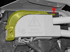
- Pull up on the tab on the front of the upper High Voltage cover, then pull the rear of the cover inboard. Remove the cover.
-
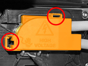
Release the 2 locking tabs to remove the lower HV cover.
NoteThe following picture shows an older version, the newer version might have a sliding tab
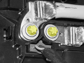
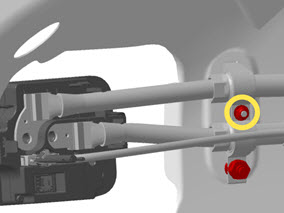
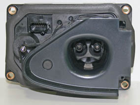
- Release the 2 bolts that secure the HV cables to the charge port (torque 9 Nm).
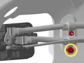
- Release the nut that secures the base of the HV cable bracket to the body (5.5 Nm).
-
Loosen the nut that secures the center of the cable bracket to the body (torque
4 Nm).
NoteIt is not necessary to fully release this nut.
- Move the HV cables away from the charge port.
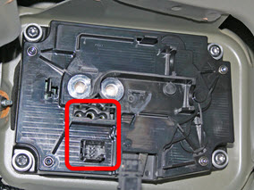
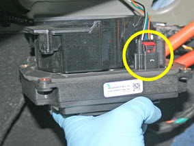
- Disconnect the 2 low voltage harnesses from the charge port.
-
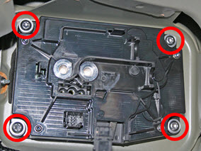
Release the 4 bolts that secure the charge port to the body (torque 5 Nm), but
do not remove it at this time.
CAUTIONDo not over-tighten the bolts during installation to prevent water leaks inside the trunk area.
- Disconnect the harness that leads to the charge port door motor.
- Remove the charge port from the vehicle.
Installation
Installation procedure is the reverse of removal, except for the following:
- Before installing the charge port, ensure that the grommet is fully seated in the door actuator.
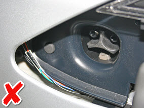
- Ensure that the wires for the charge port door motor are routed beneath the
charge port. CAUTIONDo not let the wires become pinched by the corner of the charge port.
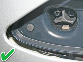
- Ensure that the charge port is flush with the body panels.
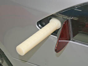
- Before securing the HV cables to the charge port, insert the charge port alignment tool into the charge port.
- Ensure that both low voltage harnesses are fully seated.
- Ensure that both the upper and lower HV covers are fully seated.
- Test the charge port door for proper fit and operation. Adjust the charge port door as necessary.
- If the vehicle does NOT have a PLC relay installed, update the vehicle firmware.
See Firmware Update.TIpTo check if a PLC relay is installed:
- Vehicle Touchscreen
- 1. On the vehicle touchscreen, touch Controls > Software > Additional vehicle information and inspect the “CCS adapter support” field.
- If “CCS adapter support” is "Enabled", a PLC relay is installed.
- If “CCS adapter support” is not displayed, check for the PLC relay using Toolbox 3.
- Toolbox 3
- Connect a laptop with Toolbox 3 to the vehicle. See Toolbox 3 (Connect and Disconnect).
- Unlock the vehicle gateway. See Gateway Unlock.
- Display the vehicle's gateway "PlcAdapterType" configuration parameter to see if the value is "GEN3_EU_CP". If yes, then a PLC relay is installed. See Gateway Configuration (Display and Change).
- Disconnect the laptop with Toolbox 3 from the vehicle. See Toolbox 3 (Connect and Disconnect).
- Vehicle Touchscreen