Electromechanical Brake Booster Assembly
(Remove and Replace)
FRT No: 33201002
2024-06-25: Updated installation procedure and revised references.
2023-06-16: Replaced steps for the Toolbox 3
Tools tab.
Warning
If the 12V power
supply is disconnected, do not attempt to open any doors with door glass in
closed position. Failure to follow this instruction could result in door glass
shatter.
Note
Before
disconnecting the 12V power supply, ensure that the driver’s door window is
fully open. Failure to follow this instruction could result in vehicle
lockout.
CAUTION
Use extreme caution
when handling the electromechanical brake booster assembly. Do not touch the input
rod, pedal travel sensor connector, or ECU connector unless otherwise noted.
Removal
CAUTION
Use extreme
caution when handling the electromechanical brake booster assembly. Do not touch
the input rod, pedal travel sensor, or ECU connector unless otherwise
noted.
The brake light
switch is a one time use component. Ensure that a new switch is used during
reinstallation.
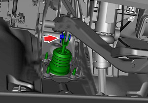
From inside the vehicle, remove
the spring clip from the clevis pin.
Depress the brake pedal for
clearance and remove the clevis pin.
Place suitable absorbent material
underneath the brake booster assembly and hydraulic lines.
Remove the brake fluid reservoir
cap.
Using a syringe, remove all fluid
from the reservoir.
Warning
Do not use a
syringe that has been used for oils or other petroleum products. Even trace
amounts of petroleum-based fluids can damage seals throughout the brake system,
leading to brake failure.
CAUTION
If brake fluid is spilled on a painted
surface, wash off immediately with clean water.
Note
Place suitable absorbent material around the affected area to absorb any
possible fluid spillage.
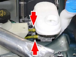
Release the nuts (x2) that secure
the front and rear hydraulic lines to the master cylinder (torque 20 Nm).
CAUTION
If brake fluid is spilled on a painted
surface, wash off immediately with clean water.
Plug the pipe connections to
prevent ingress of moisture or dirt.
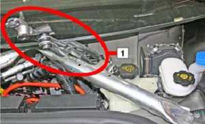
Remove the clip that secures the
LH side of the washer fluid reservoir to the crossmember.
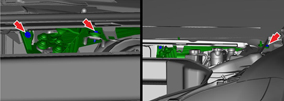
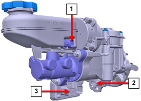
Disconnect the brake fluid level
sensor connector, pedal travel sensor connector, and ECU connector.
Note
If it is difficult to access
the sensor connectors, gently push the master cylinder towards the passenger
side of the vehicle for better access.
CAUTION
Take care not to damage
component(s).
1
Brake fluid level sensor connector
2
Pedal travel sensor connector
3
ECU connector
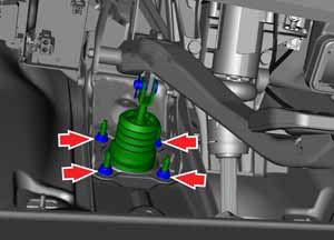
From inside the vehicle, remove
the nuts (x4) that secure the pedal to the brake booster assembly (torque 23
Nm).
CAUTION
Replace all nylon-insert
locknuts.
Using an upward motion, remove
the brake booster assembly.
CAUTION
Use extreme
caution when handling the electromechanical brake booster assembly.
CAUTION
The
electromechanical brake booster can only be supported by the ECU housing,
adapter plate, and metal housing.
Installation
CAUTION
Ensure that 12V power is
disconnected before installing the brake booster assembly.
CAUTION
Use extreme caution when
handling the brake booster assembly. Do not touch the input rod, pedal travel sensor
connector, or ECU connector unless otherwise noted.
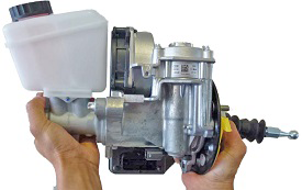
Note
Handle the booster so that the ECU
faces upward; use your left hand to support the ECU and your right hand to support the
casting.
Note
Clean the affected areas before
installation.
Have an assistant hold the brake pedal
assembly away from the booster assembly input shaft, then carefully insert the input rod
through the hole in the bulkhead.
CAUTION
Do not allow the
input rod to contact the bulkhead.
Use new fasteners to secure the
booster to the bulkhead (torque 23 Nm).
Install the clevis pin.
Install the spring clip into the
clevis pin.
Secure the front and rear hydraulic
lines to the master cylinder (torque 18 Nm).
Fill the booster reservoir with
fluid.
Connect the 3 electrical connectors to
the booster.
In Toolbox 3,
click the Actions tab, type "IBST-Pedal" into the search
field, click PROC_IBST_X_IBST-PEDALvia Toolbox:(link), click Run, and allow the routine to
complete.
In Toolbox 3, click Dashboards > Service Tools > DTCs, and then click IBST.
Sit in the driver's seat and pump the
brake pedal several times. Check for a short, firm travel when the brakes are
applied.
Perform a road test using a series of
brake stops, including at least one full ABS stop. Ensure that there is proper brake
pedal feel and performance. If brake pedal feel is not firm, repeat the bleed
procedure.