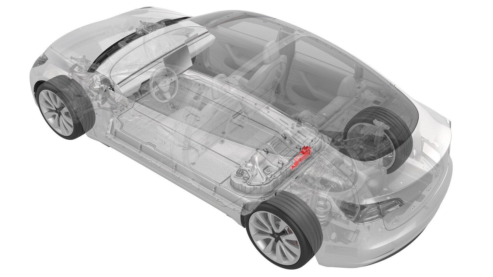
퓨즈 - 실내 히터 - HV 배터리(탈거 및 교체)
 교정 코드
16304002 1.08
메모: 절차에서 명시적으로 언급하지 않는 한 위 교정 코드 및 FRT는 연결된 절차를 포함하여 이 절차를 수행하는 데 필요한 모든 작업을 반영합니다. 명시적으로 지시하지 않는 한 교정 코드를 누적하지 마십시오.
참고: FRT와 그 생성 방법에 대한 자세한 내용은 표준 정비 작업시간을 참조하십시오. FRT 값에 대한 피드백을 제공하려면 ServiceManualFeedback@tesla.com으로 이메일을 보내십시오.
메모: 아래 절차를 수행할 때 개인 보호을(를) 참조하여 적절한 PPE를 착용했는지 확인하십시오. 안전하고 건강한 작업 사례는 인체공학적 주의 사항의 내용을 참조하십시오.
교정 코드
16304002 1.08
메모: 절차에서 명시적으로 언급하지 않는 한 위 교정 코드 및 FRT는 연결된 절차를 포함하여 이 절차를 수행하는 데 필요한 모든 작업을 반영합니다. 명시적으로 지시하지 않는 한 교정 코드를 누적하지 마십시오.
참고: FRT와 그 생성 방법에 대한 자세한 내용은 표준 정비 작업시간을 참조하십시오. FRT 값에 대한 피드백을 제공하려면 ServiceManualFeedback@tesla.com으로 이메일을 보내십시오.
메모: 아래 절차를 수행할 때 개인 보호을(를) 참조하여 적절한 PPE를 착용했는지 확인하십시오. 안전하고 건강한 작업 사례는 인체공학적 주의 사항의 내용을 참조하십시오.
필요 장비:
- 1057602-00-A 래칫, 1/4" Sq Dr, HV 절연
- 1057603-00-A 익스텐션 바, Wobble, 1/4" Dr, HV 절연
- 1057604-00-A Skt, 1/4" Sq Dr, 8mm, HV 절연
- 1057607-00-A 자석, 플렉서블, HV 절연, 18"
- 1127845-00-A 어셈블리, 서비스 커버, 보조 베이, Model 3
- 1076927-00-A 저항계, 마이크로옴, Hioki RM 3548
모든 필수 인증 교육을 완료한 기술자만 이 절차를 수행할 수 있습니다. Tesla는 타사 서비스 제공업체 기술자가 이 절차를 수행하기 전에 동등한 교육을 받을 것을 권장합니다. Tesla 기술자 요구 사항에 대한 자세한 내용이나 타사 기술자에 대한 분야별 설명은 HV Certification Requirements를 참조하십시오. 고전압 케이블, 버스바 또는 피팅을 다룰 때에는 항상 적합한 개인 보호 장비(PPE)와 클래스 0(1000V)의 최소 정격을 갖는 절연 HV 장갑을 착용해야 합니다. 추가 안전 정보는 기술 노트 TN-15-92-003고압 인식 주의 사항
을 참조하십시오.
탈거
- 점화식 배터리 차단기를 탈거합니다. 점화식 배터리 차단기(탈거 및 교체)을(를) 참조하십시오.
-
고전압 컨트롤러(HVC)를 들어 올리고, 퓨즈 액세스 절연체를 RH 보조 베이 버스 커버에 고정하는 클립을 해제하고 절연체를 탈거합니다.
-
PTC 히터 퓨즈를 RH 보조 베이 버스에 고정하는 너트를 탈거하여 폐기하고 퓨즈를 탈거합니다.
장착
- 나중에 이 절차에서 저항을 측정하는 것에 대비하여 Hioki 저항계의 영점 조정을 수행합니다. 참조 항목: 저항계(영점 조정).
-
PTC 히터 퓨즈를 RH 보조 베이 버스에 장착한 후, 새 너트를 사용해 퓨즈를 버스에 장착합니다.
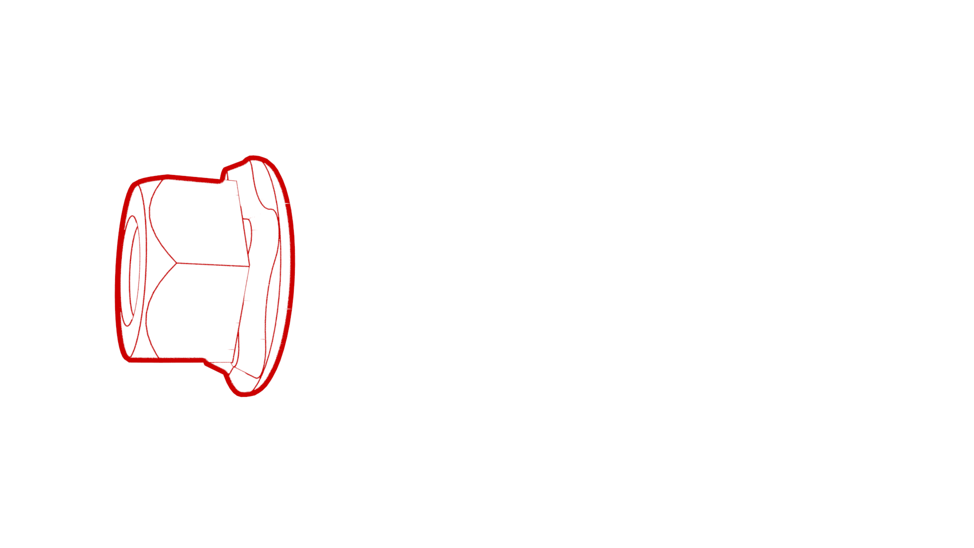 4.5 Nm (3.3 lbs-ft)
 -
Hioki 저항계를 사용해 보조 베이 버스와 PTC 히터 퓨즈 본체 LH 사이의 HV 조인트에서 저항을 측정합니다.
참고최대 허용 저항은 0.105mΩ(105μΩ)입니다. 고전압 조인트에 저항이 너무 많습니다. 패스너를 탈거하고 이소프로필 알코올로 해당 부위를 청소한 후 패스너를 다시 장착하고 다시 테스트합니다.
그림 1. 일반 측정 - 실제 버스바 및 패스너는 다르게 보일 수 있음 -
Hioki 저항계를 사용해 PTC 히터 퓨즈의 RH와 각각의 링 터미널 플레이팅 사이의 HV 조인트에서 저항을 측정합니다.
참고최대 허용 저항은 0.145mΩ(145μΩ)입니다. 고전압 조인트에 저항이 너무 많습니다. 패스너를 탈거하고 이소프로필 알코올로 해당 부위를 청소한 후 패스너를 다시 장착하고 다시 테스트합니다.
그림 2. 일반 측정 - 실제 버스바 및 패스너는 다르게 보일 수 있음 -
퓨즈 액세스 절연체를 RH 보조 베이 버스 커버에 장착하고 절연체를 커버에 고정하는 클립을 조인 후 고전압 컨트롤러(HVC)를 내립니다.
- 점화식 배터리 차단기 고정 지점에서 전압을 측정한 다음 점화식 배터리 차단기를 장착합니다. 점화식 배터리 차단기(탈거 및 교체)을(를) 참조하십시오.