커버 - 보조 베이(탈거 및 교체)
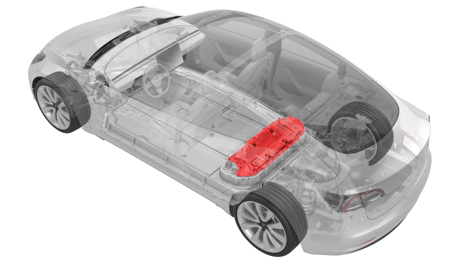 교정 코드
16101002 1.08
메모: 절차에서 명시적으로 언급하지 않는 한 위 교정 코드 및 FRT는 연결된 절차를 포함하여 이 절차를 수행하는 데 필요한 모든 작업을 반영합니다. 명시적으로 지시하지 않는 한 교정 코드를 누적하지 마십시오.
참고: FRT와 그 생성 방법에 대한 자세한 내용은 표준 정비 작업시간을 참조하십시오. FRT 값에 대한 피드백을 제공하려면 ServiceManualFeedback@tesla.com으로 이메일을 보내십시오.
메모: 아래 절차를 수행할 때 개인 보호을(를) 참조하여 적절한 PPE를 착용했는지 확인하십시오. 안전하고 건강한 작업 사례는 인체공학적 주의 사항의 내용을 참조하십시오.
- 2025-10-17: HVC 재작업 단계를 삭제했습니다. 모든 Model 3 차량이 볼케이노 브래킷이 있는 보조 커버를 사용하도록 명시했습니다.
- 2025-10-13: 보조 베이 커버를 탈거/장착하는 단계에서 차량 외부에 서서 작업하라는 경고를 추가했습니다.
- 2025-02-20: 고전압 컨트롤러(HVC) 재작업 단계를 추가했습니다.
- 2024-04-04: 보조 베이 키트 절연체 장착 및 탈거 정보를 추가했습니다.
- 2023-11-08: HV 절연 장갑 단계를 추가/업데이트했습니다.
- 2023-06-09: 페인트 펜 색상을 수정했습니다.
- 2023-05-22: 올바른 양극 DC 케이블 연결을 위한 주의사항을 추가했습니다.
- 2023-06-29: 장착 부분의 6단계에 비디오를 추가했습니다.
- 2023-07-06: 장착 부분의 11단계에 비디오를 추가했습니다.
필요 장비:
- 1127845-00-A 어셈블리, 서비스 커버, 보조 베이, Model 3
- 1059330-00-B Skt, 1/4in Dr, 5-Lobe Torx Plus 외부
- 1076971-02-A 렌치, 토크 + 앵글, 1/4" Dr
- 1108272-00-B 캡, 로직 커넥터, 인버터, 3DU
모든 필수 인증 교육을 완료한 기술자만 이 절차를 수행할 수 있습니다. Tesla는 타사 서비스 제공업체 기술자가 이 절차를 수행하기 전에 동등한 교육을 받을 것을 권장합니다. Tesla 기술자 요구 사항에 대한 자세한 내용이나 타사 기술자에 대한 분야별 설명은 HV Certification Requirements를 참조하십시오. 고전압 케이블, 버스바 또는 피팅을 다룰 때에는 항상 적합한 개인 보호 장비(PPE)와 클래스 0(1000V)의 최소 정격을 갖는 절연 HV 장갑을 착용해야 합니다. 추가 안전 정보는 기술 노트 TN-15-92-003고압 인식 주의 사항
을 참조하십시오.
탈거
- 2열 하단 시트 쿠션을 탈거합니다. 시트 쿠션 - 하단 - 2열(탈거 및 교체).
- 12V 전원을 분리합니다. 참조 항목: 12V/LV 전원(연결 해제 및 연결).
- 차량 HV 비활성화 절차를 수행합니다. 참조 항목: 차량 HV 비활성화 절차.
- 보조 베이의 LH에서 폼 커버를 탈거합니다.
- LH 2열 시트 버클을 탈거합니다. 참조 항목: 버클 - 2열 - LH(탈거 및 교체).
- 중앙 2열 버클을 탈거합니다. 참조 항목: 버클 - 2열 - 중앙(탈거 및 교체).
-
차체와 보조 베이 커버에 보조 베이 레일을 고정하는 볼트를 탈거한 다음 차량에서 레일을 탈거합니다.
-
보조 베이 커버를 새 커버로 교체하는 경우, 조정 부품(4개)를 시계 방향으로 돌려 보조 베이 커버에서 탈거합니다.
-
보조 베이 커버 내부에 고전압 컨트롤러(HVC)를 고정하는 볼트를 탈거합니다.
그림 1. 5-볼트 HVC 보조 베이 커버 그림 2. 4-볼트 HVC 보조 베이 커버 그림 3. 3-볼트 HVC 보조 베이 커버 - DCDC 패스스루에서 양극 12V 출력 케이블의 커버를 분리합니다.
-
양극 12V 출력 케이블을 DCDC 패스스루에 고정하는 너트를 탈거하여 폐기한 다음, 케이블을 패스스루에서 탈거합니다.
참고출력 케이블 끝에 있는 고무 부트의 상태를 점검하고, 부트가 녹거나 손상된 경우 교체합니다.
-
HV 절연 장갑과 가죽을 덧댄 장갑을 착용합니다.
경고장갑은 벗으라는 지침이 있을 때까지 계속 착용해야 합니다.
-
HV 배터리에 보조 베이 커버를 고정하는 볼트를 완전히 풀어 탈거합니다(가능한 경우).
참고다른 보조 베이 커버 개량품은 28, 18 또는 16볼트가 있습니다.
-
고전압 컨트롤러 커넥터에서 로직 커넥터 캡을 탈거합니다.
-
보조 베이 커버를 차량에서 탈거합니다.
경고차량 외부에 서서 보조 베이 커버를 차량에서 탈거하여 열린 HV 배터리로 떨어질 위험을 줄입니다.
-
고전압 컨트롤러 커넥터에 로직 커넥터 캡을 다시 장착합니다.
- HV 절연체 유무 여부를 검사합니다. 절연체가 없거나 부분적으로만 있는 경우 보조 베이 절연체 키트를 사용하여 절연체 캡을 HV 배터리에 장착하여 고전압이 흐르는 지점을 덮습니다. 참조 항목: 절연체 - HV 배터리(장착 및 탈거).
-
보조 베이 내부에 냉각수가 누수되는지 육안으로 검사합니다.
참고주로 검사할 부분은 냉각수 주입 및 배출 튜브, 피팅 및 보조 베이 둘레입니다.경고냉각수 누수가 발견되는 경우에는 툴박스 세션을 에스컬레이션합니다.
장착
- IPA 천으로 보조 베이 커버 개스킷 표면 및 HV 배터리의 접합면을 청소합니다.
-
보조 베이 커버 개스킷과 HV 배터리 접합면의 상태를 육안으로 검사하여 균열, 절단, 패임, 마모 또는 씰에 영향을 줄 수 있는 손상이 있는지 점검합니다.
참고개스킷의 손상이 심하면 보조 베이 커버를 교체합니다. 씰에 영향을 줄 수 있는 경미한 손상(페인트 포함)이 있을 경우 지침에 따라 보조 베이 공기 누출 테스트를 수행합니다.
- IPA 천으로 고전압 컨트롤러(HVC) 마운팅 볼트 구멍 및 보조 베이 커버 볼트 구멍의 내측과 외측 모두에서 잔여물을 닦아냅니다.
-
고전압 컨트롤러 커넥터에서 로직 커넥터 캡을 탈거합니다.
- 절연체 키트 커버를 HV 배터리에서 모두 탈거합니다. 참조 항목: 절연체 - HV 배터리(장착 및 탈거).
-
보조 베이 커버를 HV 배터리에 장착한 후, 볼트를 손으로 조입니다.
경고차량 밖에서 보조 베이 커버를 HV 배터리에 장착하여 열린 HV 배터리로 떨어질 위험을 줄입니다.참고다른 보조 베이 커버 개량품은 28, 18 또는 16볼트가 있습니다.
- HV 절연 장갑을 벗습니다.
-
고전압 컨트롤러 커넥터에 로직 커넥터 캡을 다시 장착합니다.
-
그림의 순서대로 보조 베이 커버 볼트를 규격 토크로 조이고, 주황색 페인트 펜을 사용해 규격 토크로 조였다는 표시를 합니다.
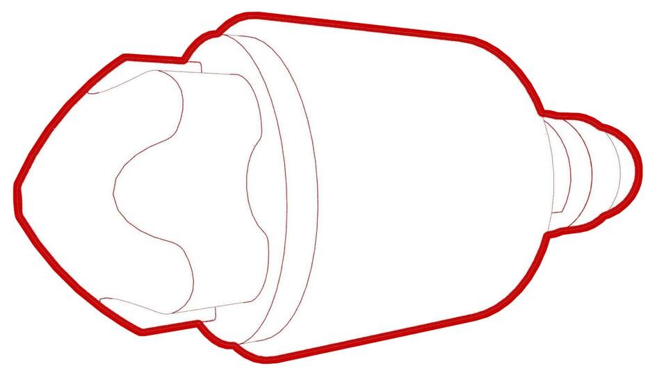 8 Nm (5.9 lbs-ft)경고자성이 없는 외부 Torx E10 5-Lobe 소켓을 사용합니다. 자석이 있는 소켓은 완전히 고정되지 않으며 볼트 헤드를 벗길 수 있습니다.TIp다음 공구를 사용하는 것이 좋습니다.
- 외부 Torx E10 5-Lobe
- 4인치 익스텐션
- 래칫/토크 렌치
그림 4. 28-볼트 보조 베이 커버 규격 토크로 조이기 순서 그림 5. 18-볼트 보조 베이 커버 규격 토크로 조이기 순서 그림 6. 16-볼트 보조 베이 커버 규격 토크로 조이기 순서 -
양극 12V 출력 케이블을 DCDC 패스스루에 연결하고, 새 너트를 장착하여 케이블을 고정한 다음 규격 토크로 조인 후 분홍색/보라색 페인트 펜으로 너트에 표시합니다.
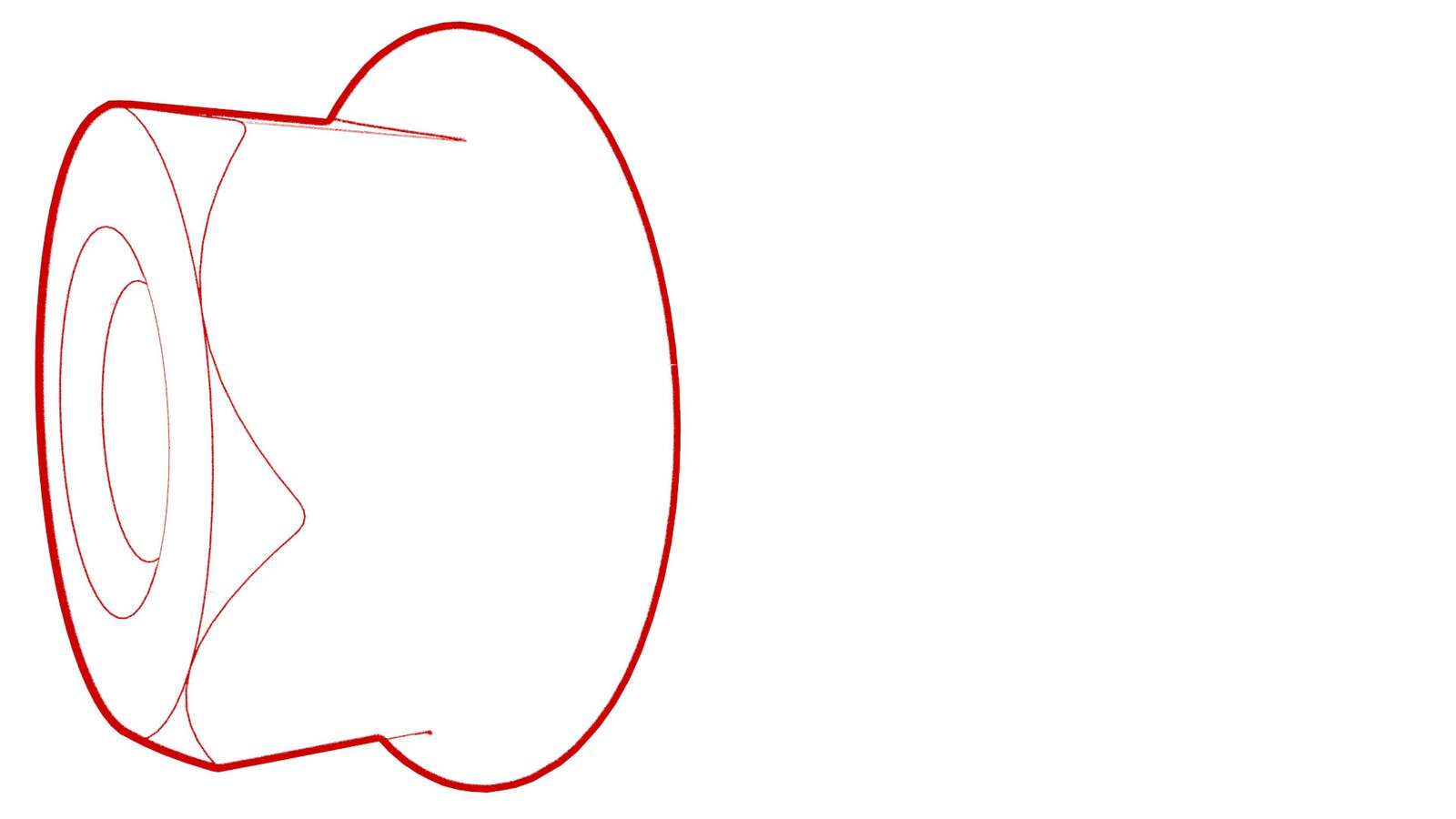 9 Nm (6.6 lbs-ft)경고고무 부트가 케이블 러그 아래에 걸리거나 케이블 러그와 너트 사이에 끼이지 않았는지 확인합니다.경고양극 출력 케이블이 DCDC 패스스루의 플라스틱 회전 방지 가장자리에 올바른 방향으로 올바르게 배치되었는지 확인합니다.
 - 탈거한 경우, DCDC 패스스루의 양극 12V 출력 케이블의 커버를 교체한 다음, 눌러서 커버를 고정합니다.
-
보조 베이 커버 내부에 고전압 컨트롤러(HVC)를 고정하는 새 볼트를 장착하고 손으로 조입니다.
경고차체 측면에서 LH 상단 A필러 트림 테더를 탈거하지 마십시오. 차체에서 테더를 탈거할 경우, 테더를 교체해야 합니다.
그림 7. 5-볼트 HVC 보조 베이 커버 그림 8. 4-볼트 HVC 보조 베이 커버 그림 9. 3-볼트 HVC 보조 베이 커버 -
표시된 순서대로 보조 베이 커버 볼트에 고전압 컨트롤러(HVC)를 규격 토크로 조이고, 주황색 페인트 펜을 사용해 규격 토크로 조였다는 표시를 합니다.
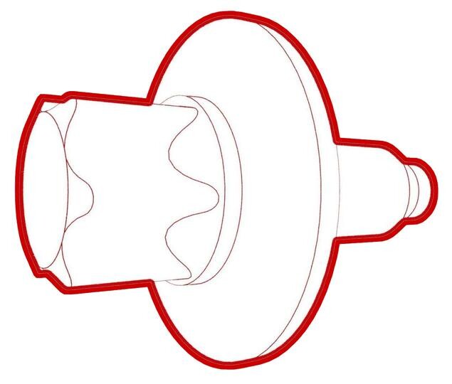 5 Nm (3.7 lbs-ft) +30 deg경고볼트 1과 2를 토크로 충분히 조이지 않으면 고전압 인터록 루프 회로가 개방됩니다.TIp다음 공구를 사용하는 것이 좋습니다.
- 외부 Torx E10
- 4인치 익스텐션
- 래칫/토크 렌치
- 각도 측정 토크 렌치
그림 10. 5-볼트 HVC 보조 베이 커버 그림 11. 4-볼트 HVC 보조 베이 커버 그림 12. 3-볼트 HVC 보조 베이 커버 -
보조 베이 커버 개스킷 또는 HV 배터리 접합면에 손상이 있는 경우, 알루미늄 테이프 새로 장착 패치를 교체한 경우 또는 다른 절차에서 보조 베이 공기 누출 테스트를 수행하라고 지시한 경우 보조 베이 공기 누출 테스트를 수행합니다. 참조 항목: 보조 베이 공기 누출 테스트.
참고보조 베이 공기 누출 테스트를 수행하는 경우 서비스 방문에 별도의 활동으로 교정 코드 16100400을 추가합니다.
-
보조 베이 커버에 조절 엘리먼트(4개)를 장착하고 시계 반대 방향으로 손으로 조여 완전히 체결되도록 합니다.
경고손으로 조이는 것만 가능합니다.
-
고전압 컨트롤러 커넥터에서 로직 커넥터 캡을 탈거합니다.
-
고전압 컨트롤러 커넥터에 전기 하네스를 연결합니다.
- 보조 베이 레일을 차체 및 보조 베이 커버에 장착하되 아직 볼트를 장착하지 않습니다.
- 중앙 2열 버클을 장착합니다. 참조 항목: 버클 - 2열 - 중앙(탈거 및 교체).
-
이 비디오에서는 2열 LH 시트 버클을 2열 중앙 안전벨트 앵커에 올바르게 적층하는 방법을 보여 줍니다.
-
2열 중앙 안전벨트 앵커를 2열 LH 내측 보조 베이 레일에 벨트가 RH에 있도록 배치합니다.
-
안번벨트가 꼬이지 않고 2열 시트 등받이에 평평하게 놓였는지 확인합니다.
-
2열 LH 시트 버클 브래킷의 가이드 핀을 2열 LH 내측 보조 베이 레일의 구멍에 배치하고 가이드 핀을 앵커의 슬롯에 정렬하여 브래킷을 앵커의 아래로 돌립니다.
-
새 볼트를 장착하여 시트 버클 브래킷, 안전벨트 앵커 및 내측 보조 베이 레일을 차체에 고정합니다.
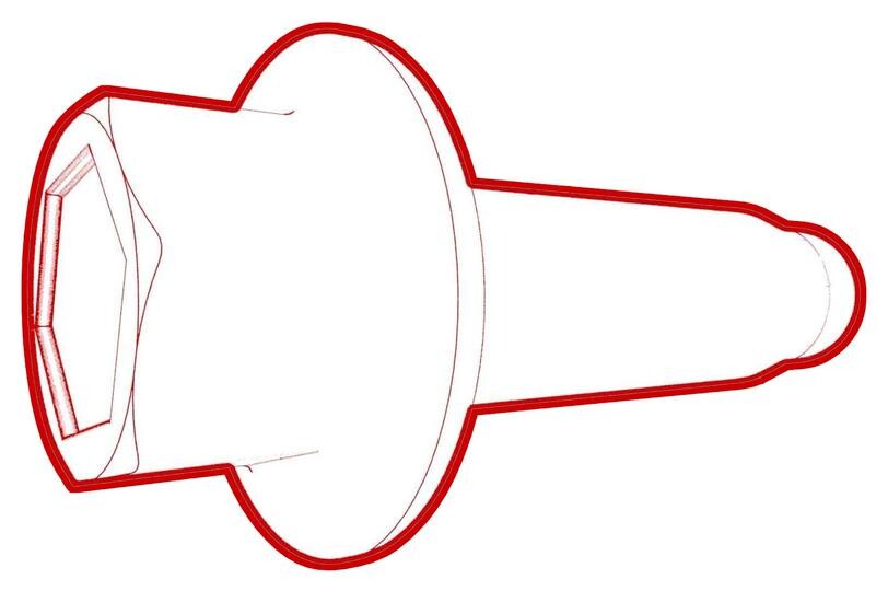 40 Nm (29.5 lbs-ft)
 -
적층을 확인하십시오.
설명선 설명 1 상단의 LH 2열 버클 2 가운데의 중앙 2열 안전벨트 앵커 3 하단의 LH 내측 보조 베이 레일 -
전기 커넥터의 암 쪽을 차체 스터드에 고정하는 플라스틱 브래킷을 장착합니다.
-
전기 하네스를 LH 후면 안전벨트 버클 커넥터에 연결합니다.
-
레일을 보조 베이 커버 및 차체에 고정하는 볼트를 장착하고 손으로 조입니다.
-
볼트를 규격 토크로 조입니다.
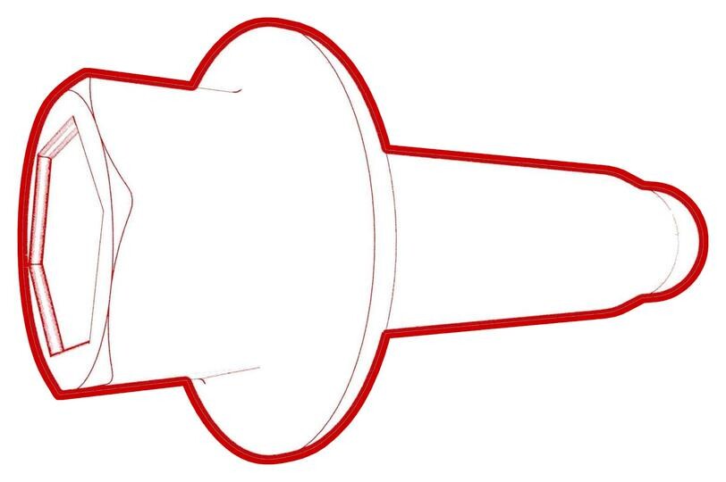 24 Nm (17.7 lbs-ft)
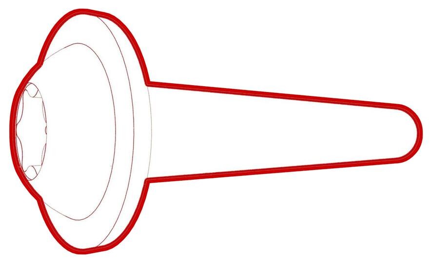 24 Nm (17.7 lbs-ft)
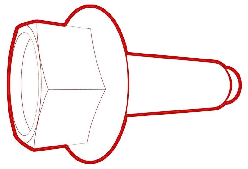 24 Nm (17.7 lbs-ft)
 - 보조 베이 LH에 폼 커버를 장착합니다.
- 2열 하단 시트 쿠션을 장착합니다. 참조 항목: 시트 쿠션 - 하단 - 2열(탈거 및 교체).
- 12V 전원을 연결합니다. 참조 항목: 12V/LV 전원(연결 해제 및 연결).