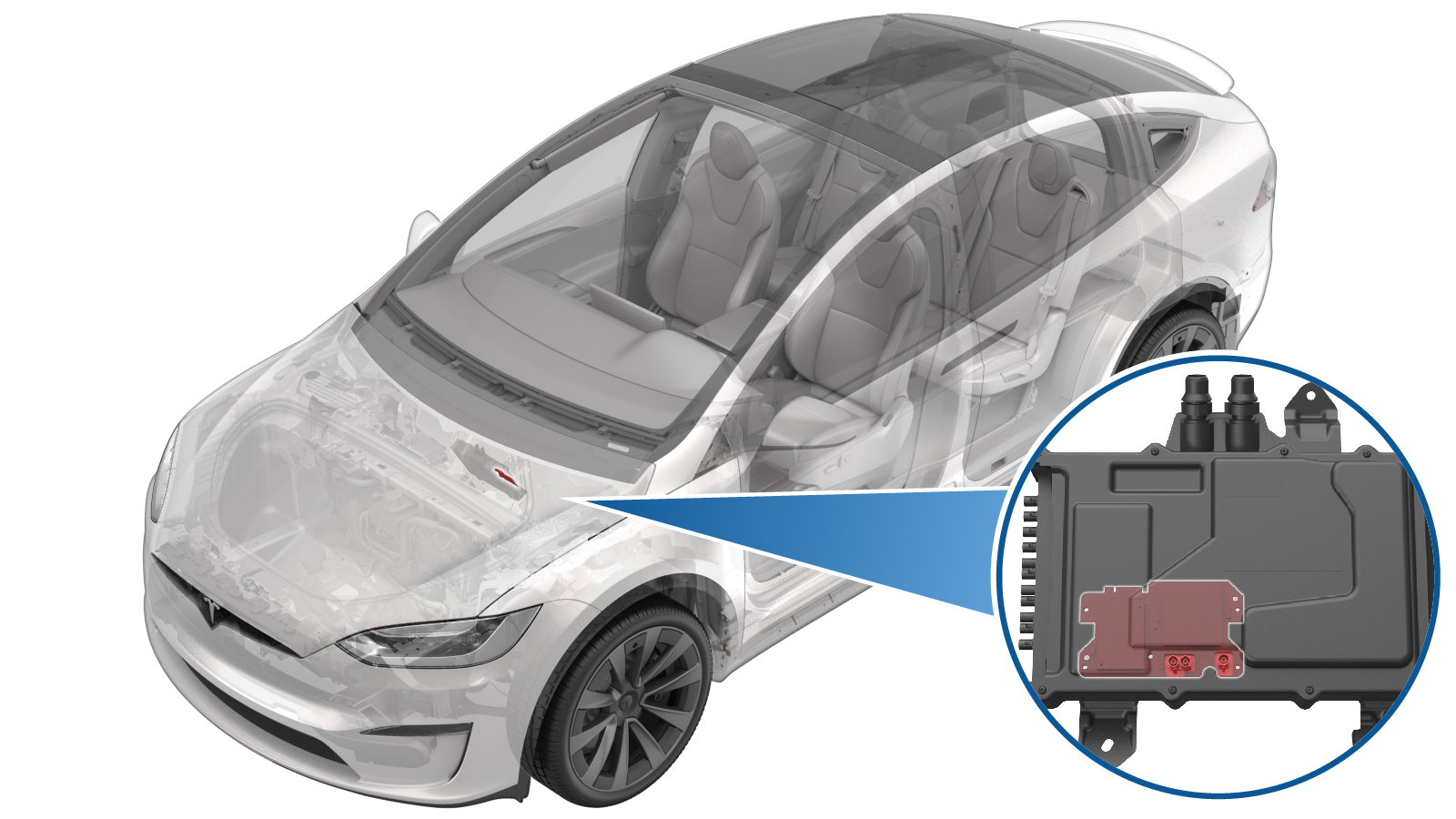
Connectivity Board - Car Computer (Remove and Replace)
 Correction code
21152902
NOTE: Unless otherwise explicitly
stated in the procedure, the above correction code and FRT reflect all of the work
required to perform this procedure, including the linked procedures. Do not stack correction codes unless
explicitly told to do so.
NOTE: See Flat Rate Times to learn
more about FRTs and how they are created. To provide feedback on FRT values, email ServiceManualFeedback@tesla.com.
NOTE: See Personal Protection to make sure proper PPE is worn when
performing the below
procedure.
Correction code
21152902
NOTE: Unless otherwise explicitly
stated in the procedure, the above correction code and FRT reflect all of the work
required to perform this procedure, including the linked procedures. Do not stack correction codes unless
explicitly told to do so.
NOTE: See Flat Rate Times to learn
more about FRTs and how they are created. To provide feedback on FRT values, email ServiceManualFeedback@tesla.com.
NOTE: See Personal Protection to make sure proper PPE is worn when
performing the below
procedure.
-
Open LH front door
-
Lower LH and RH front windows
-
Open RH front door
-
Move RH front seat backward
-
Open hood
NoteVia center display > Controls > Frunk Open
-
Power off vehicle via center display
NoteControls > Safety & Security > Power Off
-
Remove rear underhood apron
Note11x clips, 2x datums
-
Disconnect LV battery connector and First Responder Loop
Note2x connectors, Lift up and release green locking tab, Pull black connector lock outwards to release connection, Release red lock tab on FRL
-
Remove RH front floor mat
-
Remove RH footwell cover
Note3x magnets, 1x connector, 4x datums
-
Remove RH console side carpet
Note11x clips, 2x datums
-
Remove RH front door sill trim panel
Note8x clips, 3x datums
-
Remove RH IP end cap
Note3x clips
-
Remove RH mid A-pillar trim
Note2x clips, 3x datums, Release clips from upper A-pillar and IP sub assembly, Lift mid A-pillar trim out of lower A-pillar trim
-
Remove RH lower A-pillar trim
Note1x bolt, T25, 5 Nm, 2x clips, 1x datum
-
Fold RH front cabin carpet aside for access
-
Release harness from RH footrest panel
Note1x clip
-
Release RH footrest panel
Note2x bolts, 10mm, 5 Nm, 2x nut, 10mm, 5 Nm
-
Remove RH footrest panel
NoteFold RH primary support carpet up, Rotate RH footrest panel out of vehicle
-
Release connection at LH side of AP motherboard
Note1x connector, Release antenna connector that crosses in front of car computer cover (Brown connector), Release lock on connector before removal
-
Release connector to connectivity module
Note1x connector, Move release lock rearward before removal
-
Put on ESD wrist strap and connect to vehicle ground
-
Remove the car computer top cover fasteners
Note9x screws, T10, 1.4 Nm, Discard after removal, Power tools recommend to reduce time required
-
Remove car computer cover
-
Remove the connectivity board mounting screws
Note6x screws, T10, 0.7 Nm, Discard after removal
-
Slide the connectivity board down to separate connector and remove
Note1x connector, Ensure full disengagement of connectivity board before attempting to remove
-
Slide the connectivity board in to the PCB connector
Note1x connector, 1x datum, Align datum with slot in connectivity card and fully engage
-
Install mounting screws to secure connectivity board
Note6x screws, T10, 0.7 Nm, Install new fasteners
-
Install car computer cover
-
Install top cover mounting screws
Note9x screws, T10, 1.4 Nm, Install new screws
-
Remove the ESD wrist strap
-
Install connector to connectivity module
Note1x connector, Slide lock underneath connector
-
Install connection at LH side of AP motherboard
Note1x connector
-
Connect First Responder Loop and LV battery connector
Note2x connectors, Secure FRL first, Seat LV battery connection and push black connector lock inwards to secure, Engage upper locking tab when fully seated
-
Install rear underhood apron
Note11x clips, 2x datums
-
Close hood
-
Install RH footrest panel
NoteRotate RH footrest panel onto vehicle, Fold RH primary support carpet down
-
Secure RH footrest panel
Note2x bolts, 10mm, 5 Nm, 2x nut, 10mm, 5 Nm
-
Secure harness to RH footrest panel
Note1x clip
-
Fold RH main carpet back into place
-
Install RH footwell cover
Note3x magnets, 4x datums, 1x connector
-
Install RH lower A-pillar trim
Note1x bolt, T25, 5 Nm, 2x clips, 1x datum
-
Install RH mid A-pillar trim
Note2x clips, 3x datums, Verify weather seal is seated properly
-
Install RH IP end cap
Note3x clips
-
Install RH front door sill trim panel
Note8x clips, 3x datums
-
Install RH front floor mat
-
Move RH front seat to original position
-
Calibrate RH falcon wing door
NoteHold the upper B-pillar button in the down position to manually calibrate
-
Raise RH front window
-
Close RH front door
-
Calibrate LH falcon wing door
NoteHold the upper B-pillar button in the down position to manually calibrate
-
Raise LH front window
-
Close LH front door
-
Verify BT, WiFi, and LTE are functioning properly