Module - Rear Door Electromechanical Controller - LH (Remove and Replace)
 Correction code
11335022
1.32
NOTE: Unless otherwise explicitly
stated in the procedure, the above correction code and FRT reflect all of the work
required to perform this procedure, including the linked procedures. Do not stack correction codes unless
explicitly told to do so.
NOTE: See Flat Rate Times to learn
more about FRTs and how they are created. To provide feedback on FRT values, email ServiceManualFeedback@tesla.com.
NOTE: See Personal Protection to make sure proper PPE is worn when
performing the below
procedure.
Correction code
11335022
1.32
NOTE: Unless otherwise explicitly
stated in the procedure, the above correction code and FRT reflect all of the work
required to perform this procedure, including the linked procedures. Do not stack correction codes unless
explicitly told to do so.
NOTE: See Flat Rate Times to learn
more about FRTs and how they are created. To provide feedback on FRT values, email ServiceManualFeedback@tesla.com.
NOTE: See Personal Protection to make sure proper PPE is worn when
performing the below
procedure.
Remove
- Remove the headliner. See Headliner (Remove and Install).
-
Disconnect the electrical connectors
(x4) for the LH and RH rear door electromechanical controller modules.
-
Disconnect the coaxial connector from
the center spine closeout panel.
-
Remove the bolts (x8) that attach the
center spine closeout panel to the body.
 3.5 Nm (2.6 lbs-ft)TIpUse of the following tool(s) is recommended:
- 10 mm socket
NoteDo not allow the center spine closeout panel to hang on the electrical harness. -
Release the clips (x5) from the center
spine closeout panel, and then remove the panel.
-
Release the electrical connectors (x5)
and clips (x3) that are attached to the LH rear door electromechanical controller
module.
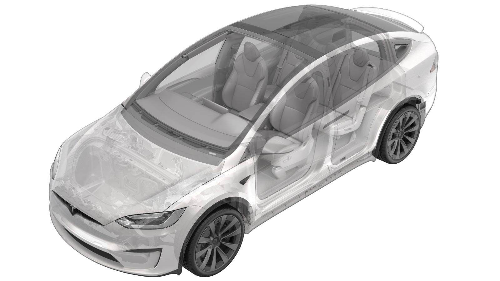
NoteThere are two rear door electromechanical controller modules, both mounted on the center spine inside the vehicle. The module in the front controls the LH rear door, and the module in the rear controls the RH rear door.
-
Remove the bolts (x3) that attach the
LH rear door electromechanical controller module, and then remove module from the
vehicle.1.5 Nm (1.1 lbs-ft)TIpUse of the following tool(s) is recommended:
- Torx T20 socket
Install
-
Position the LH rear door
electromechanical controller module in the vehicle and install the bolts (x3).1.5 Nm (1.1 lbs-ft)TIpUse of the following tool(s) is recommended:
- Torx T20 socket
-
Secure the clips (x3), and then
install the electrical connectors (x5).
-
Position the center spine closeout
panel in the vehicle, and then secure the clips (x2).
Note2x clips
-
Install the bolts (x8) that attach the
center spine closeout panel to the body.3.5 Nm (2.6 lbs-ft)TIpUse of the following tool(s) is recommended:
- 10 mm socket
-
Secure the clips (x3) that attach the
electrical harnesses to the center spine closeout panel.
-
Install the electrical connectors (x4)
for the LH and RH rear door electromechanical modules.
- Install the headliner. See Headliner (Remove and Install).
-
Verify that the bluetooth, Wi-Fi, and
the LTE are functioning properly.
- Connect a laptop with Toolbox to the vehicle. See Toolbox (Connect and Disconnect).
- Using Toolbox, click the Actions/Autodiag tab, and then search for ‘FALCON.'
-
Click
TEST-SELF_BCFALCD_DRV_FALCON-CONTROLLERvia Toolbox: (link), and then click
Run. Allow routine to complete.
NoteClick the X at top right of window to close once completed.
- Click the Actions tab, and then search for "Service-Redeploy."
-
Click SERVICE CAN
REDEPLOY, and then click Run. Allow the routine to
complete.
NoteClick the X at top right of window to close once completed.NoteRoutine will state pass but update will continue to run in the background. UI will show update progress.
-
Calibrate the rear doors.
NoteIf the "Calibration Needed" message appears on the vehicle touchscreen, touch and hold Calibrate to calibrate the rear doors
- Disconnect the laptop from the vehicle. See Toolbox (Connect and Disconnect).
- Update the vehicle firmware. See Firmware Update.
- Verify that the rear doors open and close as expected.