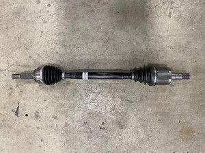
Halfshaft - Rear Drive Unit - LH (Remove and Replace)
 Correction code
40302002
1.20
NOTE: Unless otherwise explicitly
stated in the procedure, the above correction code and FRT reflect all of the work
required to perform this procedure, including the linked procedures. Do not stack correction codes unless
explicitly told to do so.
NOTE: See Flat Rate Times to learn
more about FRTs and how they are created. To provide feedback on FRT values, email LaborTimeFeedback@tesla.com.
NOTE: See Personal Protection to make sure proper PPE is worn when
performing the below
procedure.
Correction code
40302002
1.20
NOTE: Unless otherwise explicitly
stated in the procedure, the above correction code and FRT reflect all of the work
required to perform this procedure, including the linked procedures. Do not stack correction codes unless
explicitly told to do so.
NOTE: See Flat Rate Times to learn
more about FRTs and how they are created. To provide feedback on FRT values, email LaborTimeFeedback@tesla.com.
NOTE: See Personal Protection to make sure proper PPE is worn when
performing the below
procedure.
- 2024-06-04: Updated EPB Service Mode reference.
- 2024-01-19: Updated EPB Service Mode reference.
- Place the vehicle into EPB Service Mode. See Park Brake Caliper - Release.
- Remove the LH rear wheel center cap.
- Use the breaker bar to loosen the LH rear wheel lug nut covers.
-
Raise partially and lower onto lock. See Raise Vehicle - 2 Post Lift.
NoteSet vehicle to comfortable working height, Make sure there's an audible click of the locks on both sides before lowering, otherwise vehicle may tilt to the side
-
Remove the nuts (X5) that attach the LH
rear wheel to vehicle.
 175 Nm (129.1 lbs-ft)
-
Using the small flat head screw driver
to disconnect EPB harness connector (X1) to the LH caliper motor.

-
Using the small flat head screw driver to disconnect LH rear active damper
harness.
NoteTake note of original harness routing, LH and RH side are routed differently.
-
Release subframe harness from LH rear
active dampener.

-
Release harness clip from LH rear
knuckle.

-
Remove wheel speed sensor from LH rear
knuckle.
5 Nm (3.7 lbs-ft)

-
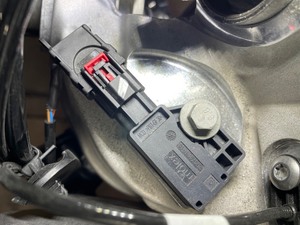
Disengage red locking tab and push down
on black tab to release connector to LH rear ANC sensor.
-
Remove bolts securing LH rear knuckle
harness bracket and move aside.
5 Nm (3.7 lbs-ft)


-
Release LH rear stabar link from rear
stabar assembly.
55 Nm (40.6 lbs-ft)

-
Remove LH rear brake caliper from LH
rear knuckle and hang from body.
125 Nm (92.2 lbs-ft)NoteRoute caliper hose so that it does not get caught on stabar assembly.

-
Remove axle nut and discard washer
securing LH rear drive axle to hub assembly.
245 Nm (180.7 lbs-ft)NoteDiscard after removal.

-
If installed, remove and discard
the bolt that attaches the brake rotor to the hub.
NoteA new bolt will not be installed.TIpUse of the following tool(s) is recommended:
- 13 mm socket

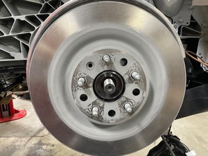
-
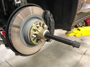
Install the hub puller onto the LH rear
brake rotor, and hand tight.
-
Remove hub puller from LH rear hub
assembly.
-
Remove rotor from LH rear knuckle.


-
Remove nut securing LH rear air spring
module to LH rear knuckle.
150 Nm (110.6 lbs-ft)NoteDo not remove the bolt.

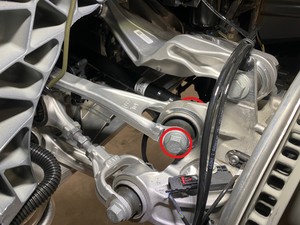
-
Remove bolt securing LH rear upper fore
link to knuckle.
150 Nm (110.6 lbs-ft)

-
Remove bolt securing LH rear toe link to
knuckle.
150 Nm (110.6 lbs-ft)

-
Remove bolt securing LH rear lower fore
link to knuckle.
150 Nm (110.6 lbs-ft)

-
Remove LH rear knuckle assembly from
vehicle.
NoteRecommend assistance.


-
Release LH halfshaft from RDU and remove
from vehicle.
Installation
-
Position halfshaft into vehicle for
installation.

-
Pull on the inner halfshaft cup to
confirm that the circlip is locked into place. If the halfshaft detaches from the drive
unit then reinstall the halfshaft and then test that it is fully seated.
CAUTIONIf reinstalling the halfshaft to the drive unit:
- Take care not to damage or displace the oil seals.
- Make sure that the opening of the snap rings are facing towards the bottom of the drive unit.
- Carefully push the halfshaft into the drive unit until there is an audible "click" from the halfshaft stub contacting the pinion shaft.
- There will be a slight pulling sensation on the halfshaft as the halfshaft circlip locks into place.
- Pull on the inner halfshaft cup to confirm that the circlip is locked into place. If the halfshaft detaches from the drive unit then reinstall the halfshaft and then test that it is fully seated.

-
Apply approximately 1 gram of Molykote M-77 Lubricant Paste only to the hub mating face on the
outboard side of the LH rear drive unit halfshaft.
TIpA bent acid brush can be of assistance.CAUTIONDo not apply any lubricant to the halfshaft splines. If lubricant is mistakenly applied, wipe the splines clean with a shop towel.

-
Position LH rear knuckle for
installation.
NoteRecommend assistance, If required, use a bolt or punch to temporarily hold knuckle in place.


-
Install bolt securing LH rear lower
aft link to knuckle
150 Nm (110.6 lbs-ft)

-
Install bolt securing LH rear toe link
to knuckle.
150 Nm (110.6 lbs-ft)

-
Install bolt securing LH lower fore
link to knuckle
150 Nm (110.6 lbs-ft)NoteUse a pry bar to help align fastener hole to knuckle.

-
Install bolt securing LH upper fore
link to knuckle.
150 Nm (110.6 lbs-ft)

-
Install bolt securing LH rear upper
aft link to knuckle.
150 Nm (110.6 lbs-ft)

-
Install bolt securing LH rear air
spring module to LH rear knuckle
150 Nm (110.6 lbs-ft)NotePry upwards on valve body to align fastener holes. Use deadblow as a leverage against the upper arms and knuckle.
-
Position rotor onto LH rear
knuckle.
-
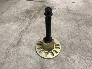
Install hub jack adapter onto LH rear
hub, and hand tight.
NoteUsed modified hydraulic hub tool if correct adapter is not available
-
Position and raise support stand to
simulate LH rear suspension at ride height.

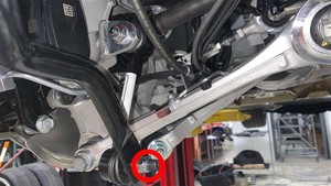
-
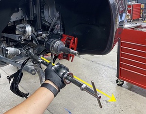
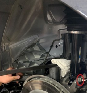
Measure the distance from the upper
fore link to the bolt on the frame rail to make sure LH suspension is set to ride
height.
NoteDistance should be 85mm +/- 5mm.

-
Torque bolt securing LH rear lower aft
link to knuckle.
150 Nm (110.6 lbs-ft)NoteMark with paint pen.

-
Torque bolt securing LH rear toe link
to knuckle.
150 Nm (110.6 lbs-ft)

-
Torque bolt securing LH rear lower
fore link to knuckle.
170 Nm (125.4 lbs-ft)

-
Torque bolt securing LH rear upper
fore link to knuckle.
150 Nm (110.6 lbs-ft)
-
Torque bolt securing LH rear upper aft
link to knuckle.
150 Nm (110.6 lbs-ft)

-
Remove support stand from underneath
LH rear suspension.
NoteLower stand until suspension is unladen before removal.

-
Remove hub jack adapter from LH rear
hub.

-
Install new axle nut and washer
assembly.
245 Nm (180.7 lbs-ft)


-
Install LH rear brake caliper to
knuckle.
125 Nm (92.2 lbs-ft)

-
Secure LH rear stabar link to stabar
assembly.
55 Nm (40.6 lbs-ft)
-
Route and install bolts securing LH
rear knuckle harness bracket.
5 Nm (3.7 lbs-ft)


-
Secure connector to LH rear ANC
sensor.

-
Install wheel speed sensor to LH rear
knuckle.
5 Nm (3.7 lbs-ft)
-
Secure harness clip onto LH rear
knuckle.
-
Secure subframe harness to LH rear
active dampener.

-
Connect LH EPB caliper harness
connector.

-
Install LH rear wheel.
175 Nm (129.1 lbs-ft)

- Lower vehicle until tires are touching the ground.
-
Torque LH rear wheel.
175 Nm (129.1 lbs-ft)
-
Torque LH rear axle nut.
245 Nm (180.7 lbs-ft)
- Install LH rear wheel center cap.
-
Remove the vehicle from the lift. See Raise Vehicle - 2 Post Lift.
NoteSet vehicle to comfortable working height, Make sure there's an audible click of the locks on both sides before lowering, otherwise vehicle may tilt to the side
- Perform the Wheel Alignment check. See Four Wheel Alignment Check.