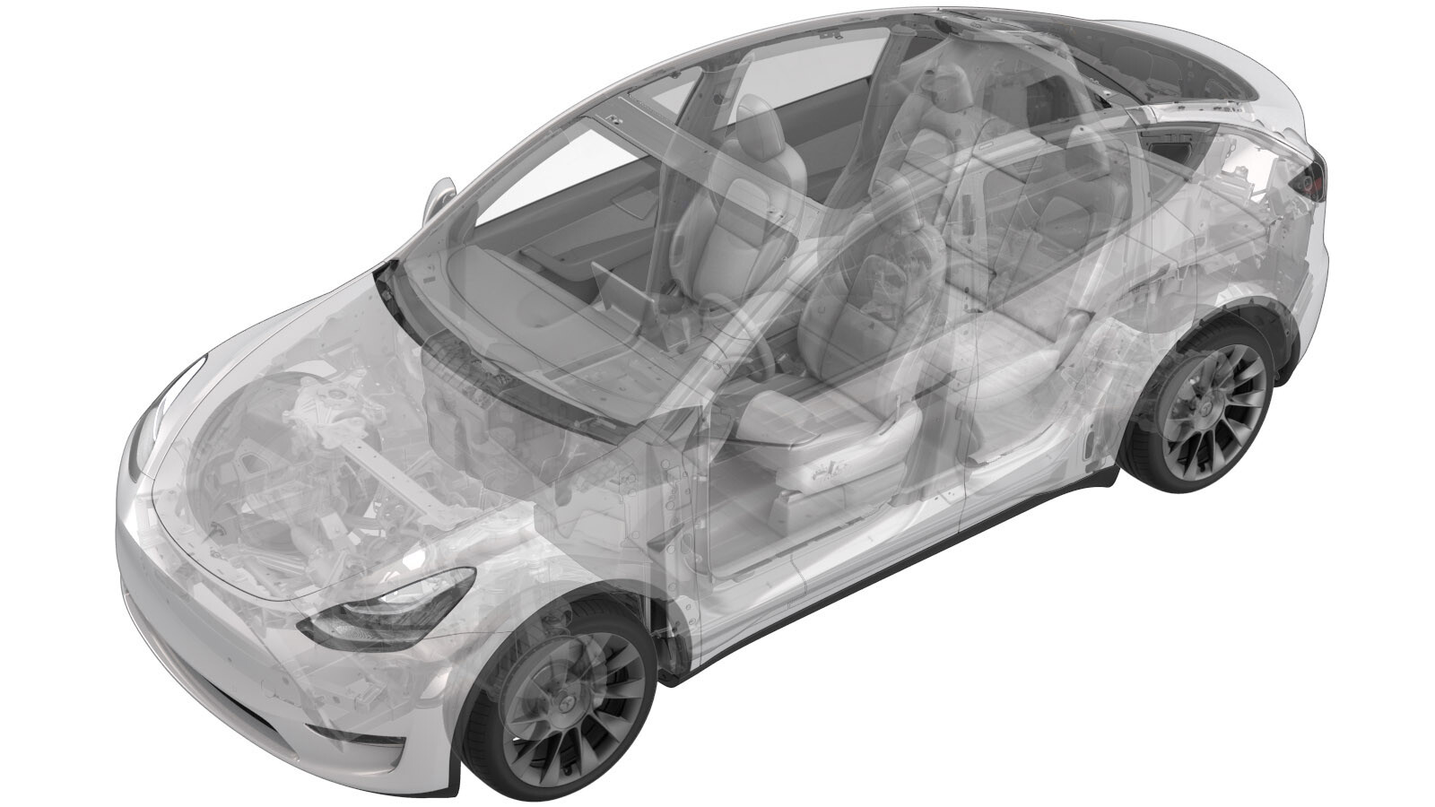
Barre omnibus - Fusible auxiliaire - Batterie HT (ensemble structural) (retirez et remplacez)
 Code de correction
16307302 2.40
REMARQUE : À moins d’indications explicites contraires dans la procédure, le code de correction et le temps forfaitaire ci-dessus représentent tout le travail à être fait pour cette procédure, notamment les procédures connexes. N’appliquez pas plusieurs codes de correction à la fois, à moins qu’il vous soit explicitement indiqué de le faire.
REMARQUE : Consultez Temps forfaitaires pour en apprendre plus à propos des temps forfaitaires et de leur création. Vous pouvez transmettre par courriel vos commentaires relatifs aux valeurs des temps forfaitaires à l'adresse ServiceManualFeedback@tesla.com.
REMARQUE : Consultez Protection individuelle pour vous assurer de porter l’équipement de protection individuelle adéquat lors vous effectuez la procédure ci-dessous. Voir Précautions ergonomiques pour consulter les pratiques de travail sécuritaires et saines.
- Open all the doors and lower all the windows.
-
Place vehicle in service mode with touchscreen
RemarqueHold Tesla T icon at top of center display for four seconds and then type "service" into dialog box
- Remove the ancillary bay cover. See Couvercle - baie auxiliaire (Ensemble structural) (retirer et remplacer).
- Retirez le sectionneur de batterie pyrotechnique. Voir Sectionneur de batterie pyrotechnique (Ensemble structural) (retirez et installez).
-
Disconnect HV controller connectors
Remarque7x connectors, Lift hinge upwards to release levered connection
-
Release harness clips from HVC hinge tray and route harness away
Remarque3x clips
-
Remove bolts securing HV controller hinge tray to HV battery
Remarque2x bolts, 8mm, 2 Nm
-
Remove HV controller and tray from ancillary bay
-
Remove 63A fuse cover
Remarque2x securing tabs
-
Disconnect HVIL connector from HV heatpump harness
Remarque1x connector
-
Remove 63A fuse from ancillary bay
Remarque2x nuts, 8mm, 2.5 Nm, Discard after removal
-
Remove inner 63A fuse from ancillary bay
Remarque2x nuts, 8mm, 2.5 Nm, Discard after removal
-
Remove ancillary bay harness from plastic bobbin stud
-
Remove bolts securing PCS to HV battery
Remarque6x bolts, 8mm, 6 Nm, Ensure ONLY the 8mm fasteners are removed, Do not remove the T30 fasteners
-
Remove ancillary bay harness from negative DC link
Remarque1x nut, 8mm, 1.5 Nm, Discard nut after removal
-
Release ancillary bay harness from tray between PCS and bobbin
Remarque1x clip
-
Remove nut securing auxiliary fuse jumper busbar
Remarque1x nut, 8mm, 2.5 Nm, Discard after removal, Slightly shift PCS to gain access to nut, Discard nut after removal
-
Remove auxiliary fuse jumper busbar
-
Install auxiliary fuse jumper busbar
-
Install nut securing auxiliary fuse jumper busbar
Remarque1x nut, 8mm, 2.5 Nm, Install new nut, Shift PCS back into original position
-
Install bolts securing PCS to HV battery
Remarque6x bolts, 8mm, 6 Nm
-
Secure ancillary bay harness onto tray between PCS and bobbin
Remarque1x clip
-
Install ancillary bay harness to negative DC link
Remarque1x nut, 8mm, 1.5 Nm, Install new nut
-
Install ancillary bay harness from plastic bobbin stud
-
Install inner 63A fuse into ancillary bay
Remarque2x nuts, 8mm, 2.5 Nm, Install new nuts
-
Install 63A fuse into ancillary bay
Remarque2x nuts, 8mm, 2.5 Nm, Install new nuts
-
Place holder- Perform Hioki measurement at the joint from 63A fuse to terminal
Remarque1x HV joint, 105µΩ or less, Perform zero adjust to Hioki meter prior to testing
-
Place holder- Perform Hioki measurement at the joint of 63A fuse to auxiliary jumper busbar
Remarque1x HV joint, 105µΩ or less, Perform zero adjust to Hioki meter prior to testing
-
Place holder- Perform Hioki measurement at the joint of inner 63A fuse to flag nut
Remarque1x HV joint, 105µΩ or less, Perform zero adjust to Hioki meter prior to testing
-
Place holder- Perform Hioki measurement at the joint of inner 63A fuse to auxiliary jumper busbar
Remarque1x HV joint, 105µΩ or less, Perform zero adjust to Hioki meter prior to testing
-
Connect HVIL connector onto tray
Remarque1x connector
-
Install 63A fuse cover
Remarque2x securing tabs
-
Position HV controller and tray into ancillary bay
-
Install bolts securing HV controller hinge tray to HV battery
Remarque2x bolts, 8mm, 2 Nm
- Mesurez la tension à travers les points de montage de déconnexion de la batterie pyrotechnique puis installez la déconnexion de la batterie pyrotechnique Voir Sectionneur de batterie pyrotechnique (Ensemble structural) (retirez et installez).
- Install the ancillary bay cover. See Couvercle - baie auxiliaire (Ensemble structural) (retirer et remplacer).
-
Exit Service Mode through UI
RemarqueControls > Service Mode > Exit Service Mode
- Raise all the windows
-
Close all the doors
RemarqueIf 12V is powered up, Unlatch rear doors before closing