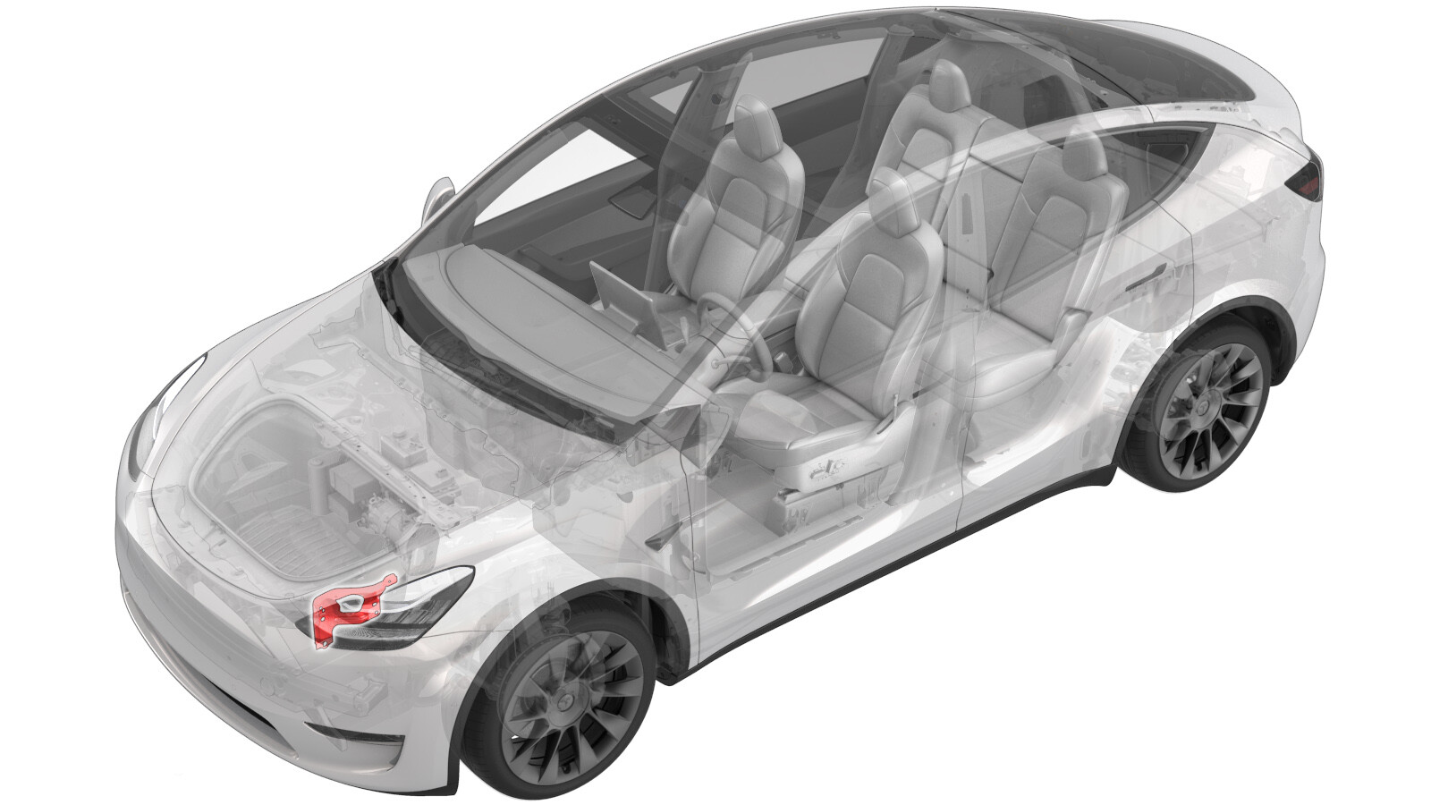
Support – Module frontal (FEM) – Gauche (retirez et remplacez)
 Code de correction
10101032 0.78
REMARQUE : À moins d’indications explicites contraires dans la procédure, le code de correction et le temps forfaitaire ci-dessus représentent tout le travail à être fait pour cette procédure, notamment les procédures connexes. N’appliquez pas plusieurs codes de correction à la fois, à moins qu’il vous soit explicitement indiqué de le faire.
REMARQUE : Consultez Temps forfaitaires pour en apprendre plus à propos des temps forfaitaires et de leur création. Vous pouvez transmettre par courriel vos commentaires relatifs aux valeurs des temps forfaitaires à l'adresse ServiceManualFeedback@tesla.com.
REMARQUE : Consultez Protection individuelle pour vous assurer de porter l’équipement de protection individuelle adéquat lors vous effectuez la procédure ci-dessous. Voir Précautions ergonomiques pour consulter les pratiques de travail sécuritaires et saines.
Spécifications de couple
| Description | Valeur de couple | Outils recommandés | Réutiliser/remplacer | Remarques |
|---|---|---|---|---|
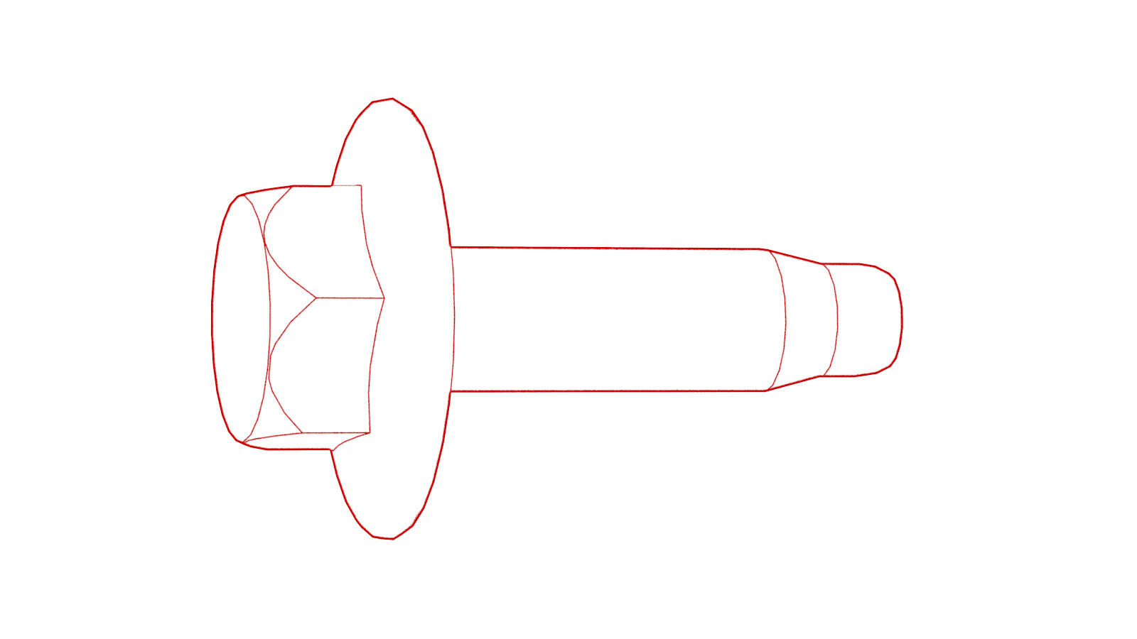
| Boulons qui fixent le module frontal gauche au véhicule |
 35 Nm (25.8 lbs-ft) |
|
Réutiliser | |
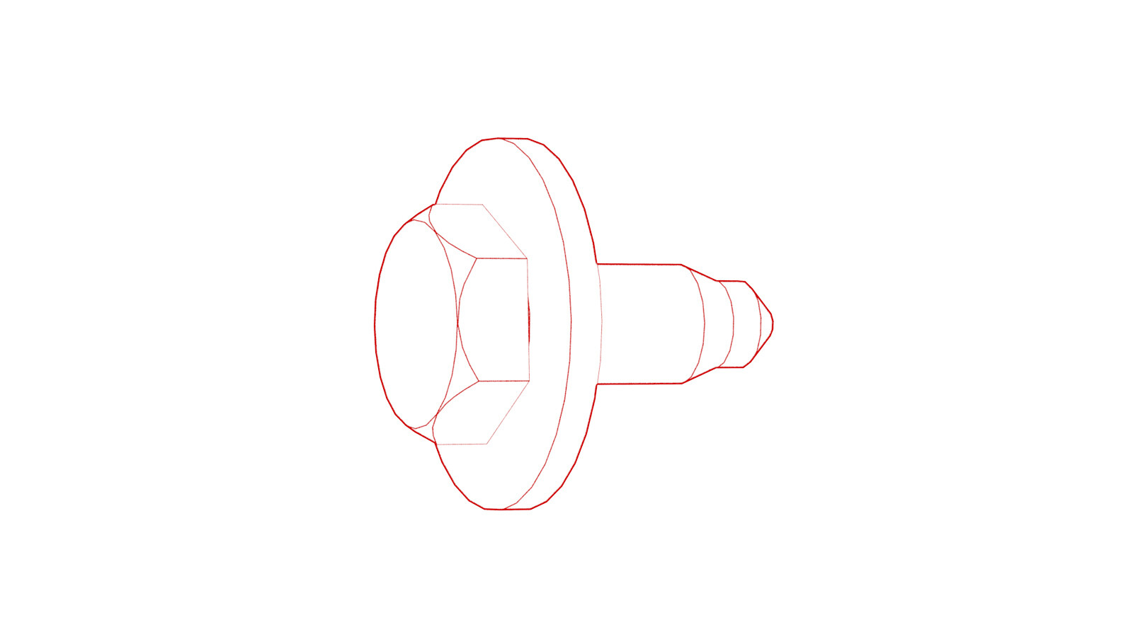
| Boulon qui fixe le support d’aile avant gauche à l’ensemble d’aile avant |
 9.8 Nm (7.2 lbs-ft) |
|
Réutiliser | |
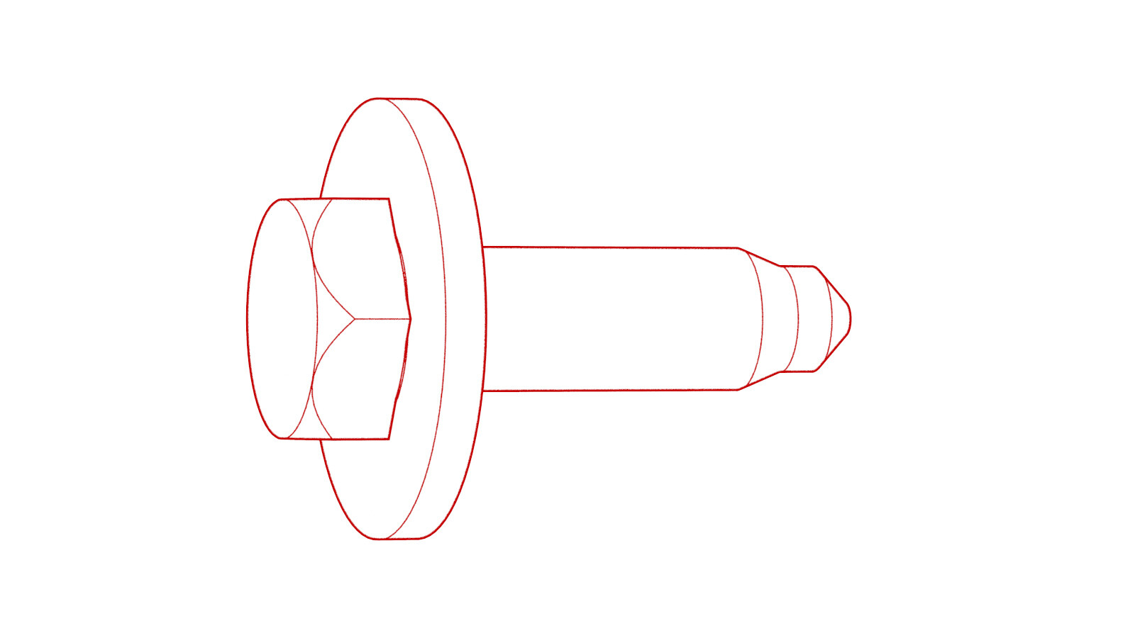
| Boulon qui fixe le module frontal gauche au support avant |
 16 Nm (11.8 lbs-ft) |
|
Réutiliser |
Retirer
- Disconnect 12V power. See Alimentation 12 V/BT (déconnectez et connectez).
- Remove the front fascia. See Carénage - avant (retirez et installez).
-
Remove the LH front ride height sensor harness from the FEM bracket assembly.
Remarque2x clips
-
Disconnect the LH front ride height sensor connector.
Remarque1x connector
-
Disconnect the LH front wheel speed sensor connector.
Remarque1x clip, 1x connector, Release locking tab
-
Disconnect the LH FEM harness connector.
Remarque1x connector, Disengage locking tab
-
Disconnect the cooling fan module connector.
Remarque1x connector, Disconnect this after coolant hose is capped to avoid coolant damaging connector
-
Release the cooling fan module harness from the FEM bracket assembly.
Remarque1x clip
-
Disconnect the connectors from horn assembly.
Remarque2x connectors
-
Disconnect the LH headlamp connector.
Remarque1x connector, Pull tab to disengage lock mechanism, Pull again to release connector, Do not press down on tab
- Remove the LH impact accelerometer. See Capteur - Accéléromètre d’impact - Pare-chocs avant - Gauche (retrait et remplacement)
-
Release the clips that attach the FEM electrical harness to the front end carrier, and then remove the harness from the front end carrier.
Remarque1x clip
-
Remove the bolts (x3) that attach the front end module bracket assembly to the vehicle.
 35 Nm (25.8 lbs-ft)TIpL'un ou plusieurs des outils suivants sont recommandés :
- Douille de 13mm
- Clé à cliquet/Clé dynamométrique
-
Remove the bolt that attach the front end module bracket to the front fender assembly.
 9.8 Nm (7.2 lbs-ft)TIpL'un ou plusieurs des outils suivants sont recommandés :
- Douille longue de 10 mm
- Rallonge électrique de 4 po
- Clé à rochet/Clé dynamométrique
-
Remove the bolt that attach the front end module bracket to the front end carrier.
 16 Nm (11.8 lbs-ft)TIpL'un ou plusieurs des outils suivants sont recommandés :
- Douille de 13 mm
- Rallonge de 6 po
- Clé à cliquet à tête flexible/clé dynamométrique à tête flexible
Installer
-
Install the bolt that attach the front end module bracket to the front end carrier.
 16 Nm (11.8 lbs-ft)TIpL'un ou plusieurs des outils suivants sont recommandés :
- Douille de 13 mm
- Rallonge de 6 po
- Clé à cliquet à tête flexible/clé dynamométrique à tête flexible
-
Install the bolt that attach the front end module bracket to the front fender assembly.
 9.8 Nm (7.2 lbs-ft)TIpL'un ou plusieurs des outils suivants sont recommandés :
- Douille longue de 10 mm
- Rallonge électrique de 4 po
- Clé à rochet/Clé dynamométrique
-
Remove the bolts (x3) that attach the front end module bracket assembly to the vehicle.
 35 Nm (25.8 lbs-ft)TIpL'un ou plusieurs des outils suivants sont recommandés :
- Douille de 13mm
- Clé à cliquet/Clé dynamométrique
-
Route the front harness through the LH FEM bracket assembly, and secure the front harness to the bracket.
Remarque1x clip
- Install the LH impact accelerometer. See Capteur - Accéléromètre d’impact - Pare-chocs avant - Gauche (retrait et remplacement)
-
Connect the LH headlamp connector.
Remarque1x connector, 1x locking tab
-
Connect the horn assembly connectors.
Remarque2x connectors
-
Connect the cooling fan module connectors and then install the clip.
Remarque1x clipRemarque1x connector
-
Connect the LH FEM harness connector.
Remarque1x connector, Engage locking tab
-
Connect the LH front ride height sensor connector and then install the clips.
Remarque2x clips, 1x connector
-
Connect the LF wheel speed sensor connector.
Remarque1x clip, 1x connector, Engage locking tab
- Install the front fascia. See Carénage - avant (retirez et installez).
- Connect 12V power. See Alimentation 12 V/BT (déconnectez et connectez).