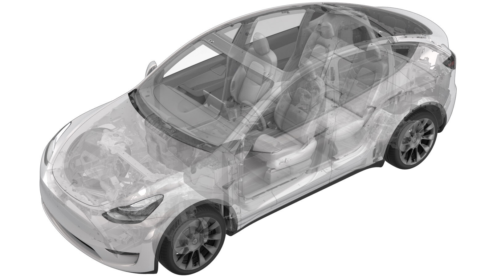
Contacteur - négatif - batterie HT (Ensemble structural) (retirez et remplacez)
 Code de correction
16302012 1.98
REMARQUE : À moins d’indications explicites contraires dans la procédure, le code de correction et le temps forfaitaire ci-dessus représentent tout le travail à être fait pour cette procédure, notamment les procédures connexes. N’appliquez pas plusieurs codes de correction à la fois, à moins qu’il vous soit explicitement indiqué de le faire.
REMARQUE : Consultez Temps forfaitaires pour en apprendre plus à propos des temps forfaitaires et de leur création. Vous pouvez transmettre par courriel vos commentaires relatifs aux valeurs des temps forfaitaires à l'adresse ServiceManualFeedback@tesla.com.
REMARQUE : Consultez Protection individuelle pour vous assurer de porter l’équipement de protection individuelle adéquat lors vous effectuez la procédure ci-dessous. Voir Précautions ergonomiques pour consulter les pratiques de travail sécuritaires et saines.
Retirer
- Open all the doors and lower all the windows.
- Place the vehicle into Service Mode. See Mode Entretien.
- Remove the ancillary bay cover. See Couvercle - baie auxiliaire (Ensemble structural) (retirer et remplacer).
- Retirez le sectionneur de batterie pyrotechnique. Voir Sectionneur de batterie pyrotechnique (Ensemble structural) (retirez et installez).
-
Disconnect the HV battery negative
contactor connectors (x2).
-
Release the clip that attaches the
ancillary bay harness to the vehicle.
-
Remove and discard the bolts (x2) that
attach the negative contactor to the busbars.
 5 Nm (3.7 lbs-ft) + 60 degreesTIpL'un ou plusieurs des outils suivants sont recommandés :
- Douille de 13 mm
-
Remove the bolts (x3) that attach the
negative contactor to the assembly tray.
 6 Nm (4.4 lbs-ft)TIpL'un ou plusieurs des outils suivants sont recommandés :
- Douille de 8 mm
-
Remove the HV battery negative pack
contactor from the ancillary bay.
Installer
-
Position the HV battery negative
contactor into the ancillary bay.
-
Install the bolts (x3) that attach the
negative contactor to the assembly tray.
 6 Nm (4.4 lbs-ft)RemarqueHand start bolts to verify the contactor is centered.TIpL'un ou plusieurs des outils suivants sont recommandés :
- Douille de 8 mm
-
Install new bolts (x2) that attach the
negative contactor to the busbars.
 5 Nm (3.7 lbs-ft) + 60 degreesTIpL'un ou plusieurs des outils suivants sont recommandés :
- Douille de 13 mm
-
Use a Hioki resistance meter to
measure the resistance at the HV joint between the newly-installed negative contactor
and the negative DC link busbar.
RemarqueThe acceptable resistance is between 0.004 mΩ (4 μΩ) and 0.050 mΩ (50 μΩ). If the resistance is greater than 0.050 mΩ (50 μΩ), there is too much resistance in the High Voltage joint. Remove the fastener, clean areas with isopropyl alcohol, install fastener back and test again. If the resistance is less than 0.004 mΩ (4 μΩ), reposition the probes and measure again.
-
Use a Hioki resistance meter to
measure the resistance at the HV joint between the newly-installed negative contactor
and the negative terminal flex assembly.
RemarqueThe acceptable resistance is between 0.004 mΩ (4 μΩ) and 0.050 mΩ (50 μΩ). If the resistance is greater than 0.050 mΩ (50 μΩ), there is too much resistance in the High Voltage joint. Remove the fastener, clean areas with isopropyl alcohol, install fastener back and test again. If the resistance is less than 0.004 mΩ (4 μΩ), reposition the probes and measure again.
-
Install the clip that attaches the
ancillary bay harness to the vehicle.
-
Connect the negative contactor
connectors (x2).
- Mesurez la tension à travers les points de montage de déconnexion de la batterie pyrotechnique puis installez la déconnexion de la batterie pyrotechnique Voir Sectionneur de batterie pyrotechnique (Ensemble structural) (retirez et installez).
- Install the ancillary bay cover. See Couvercle - baie auxiliaire (Ensemble structural) (retirer et remplacer).
- Exit Service Mode. See Mode Entretien.
- Remove the vehicle from the lift. See Soulever le véhicule - pont élévateur à 2 poteaux.
- Raise all the windows and close all the doors.