2025-04-06
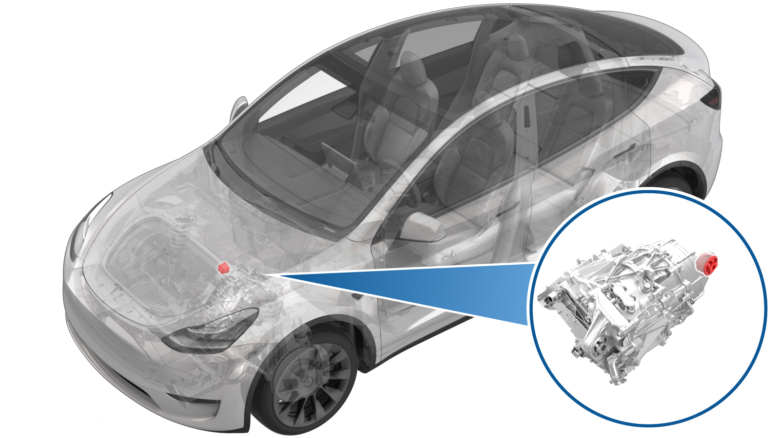
부싱 - 전륜 구동 장치 - RH(탈거 및 교체)
 교정 코드
39011102 2.70
메모: 절차에서 명시적으로 언급하지 않는 한 위 교정 코드 및 FRT는 연결된 절차를 포함하여 이 절차를 수행하는 데 필요한 모든 작업을 반영합니다. 명시적으로 지시하지 않는 한 교정 코드를 누적하지 마십시오.
참고: FRT와 그 생성 방법에 대한 자세한 내용은 표준 정비 작업시간을 참조하십시오. FRT 값에 대한 피드백을 제공하려면 ServiceManualFeedback@tesla.com으로 이메일을 보내십시오.
메모: 아래 절차를 수행할 때 개인 보호을(를) 참조하여 적절한 PPE를 착용했는지 확인하십시오. 안전하고 건강한 작업 사례는 인체공학적 주의 사항의 내용을 참조하십시오.
- 2025-04-04: Added step to refer to the suspension alignment tables to define whether an alignment check is required and, if so, what type of alignment check is required.
탈거
- Remove the front subframe assembly from the vehicle. See 서브프레임 어셈블리 - 전면(듀얼 모터)(탈거 및 장착).
-
Install the bushing tool on the RH
front drive unit bushing.
참고Use cups "K", "B", and "I" when assembling the special tool, as shown.
그림 1. Other assemblies hidden for clarity -
Turn the bearing-side bushing tool nut
with a wrench while holding the opposite nut in place.
경고Apply torque only to the bearing-side bushing tool nut.
그림 2. Apply torque only to the nut highlighted red -
When the bushing has been pushed out
of the front drive unit, separate the bushing tool, and then remove the bushing.
장착
-
부싱 공구를 설정하여 새 부싱을 압입합니다.
참고Use cups "L", "J", and "C" when assembling the special tool, as shown.참고Make sure the rubber tab is visible at the top of cup "J".
그림 3. Cups "L", "J", and "C" used to install the bushing 그림 4. Rubber tab visible at the top of cup "J" -
Turn the bearing-side bushing tool nut
with a wrench until the bushing flange makes contact with the front drive unit.
경고Apply torque only to the bearing-side bushing tool nut.참고While installing the bushing, make sure the rubber tab remains visible at the top of cup "J".
그림 5. Apply torque only to the nut highlighted red - 부싱 공구를 분리한 후 구동장치에서 부싱 공구를 탈거합니다.
-
Make sure the bushing alignment lug is
oriented to 12 o'clock.
그림 6. Other assemblies hidden for clarity - Install the front subframe assembly on the vehicle. See 서브프레임 어셈블리 - 전면(듀얼 모터)(탈거 및 장착).
- EPAS 얼라인먼트 점검(EC) 또는 4휠 얼라인먼트 점검(AC)이 필요한지 여부를 결정하려면 얼라인먼트 요구 사항 표를 참조하십시오. 얼라인먼트 점검/조정을 수행한 경우, 얼라인먼트 점검/조정 교정 코드를 SV에 별도의 활동으로 포함하십시오. 참조 항목: 얼라인먼트 요구 사항 - 서스펜션.