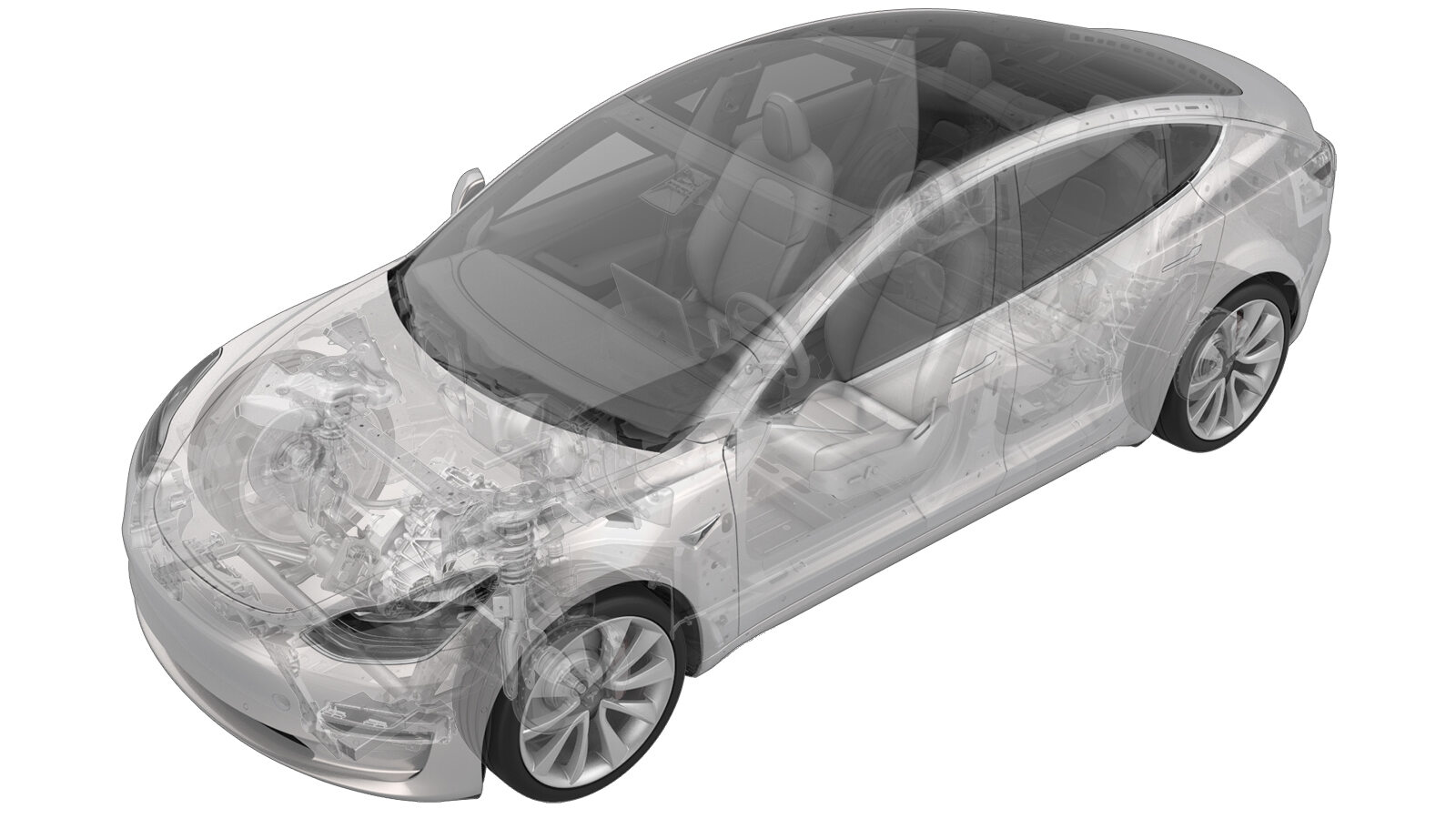
Boîte à gants - avec coussins gonflables pour les genoux (pompe à chaleur ) (retirez et remplacez)
 Code de correction
14051022
0.42
REMARQUE : À moins d’indications explicites contraires dans la procédure, le code de correction et le temps forfaitaire ci-dessus représentent tout le travail à être fait pour cette procédure, notamment les procédures connexes. N’appliquez pas plusieurs codes de correction à la fois, à moins qu’il vous soit explicitement indiqué de le faire.
REMARQUE : Consultez Temps forfaitaires pour en apprendre plus à propos des temps forfaitaires et de leur création. Vous pouvez transmettre par courriel vos commentaires relatifs aux valeurs des temps forfaitaires à ServiceManualFeedback@tesla.com.
REMARQUE : Consultez Protection individuelle pour vous assurer de porter l’équipement de protection individuelle adéquat lorsque vous effectuez la procédure ci-dessous.
REMARQUE : Voir Précautions ergonomiques pour consulter les pratiques de travail sécuritaires et saines.
Retirer
-
Open both front doors
-
Lower both front windows
-
Move RH front seat backward
-
Open hood
RemarquePress "Open" button on touchscreen to release latch, Lift lid manually
-
Remove rear apron
Remarque12x clips, Only store rear apron visible face upwards
-
Power off vehicle from center
display
RemarqueVia Controls > Safety > Power Off, Select Power Off button at warning dialogue box
-
Disconnect 12V negative terminal
Remarque1x nut, 10mm, 6 Nm, Ensure vehicle is in park, climate control system is off, and vehicle is not charging before disconnecting 12V
-
Disconnect first responder loop
Remarque1x connector, Release locking tab
-
Remove LH IP end cap
Remarque3x clips
-
Remove LH air wave bezel cap from main
decor assembly
Remarque2x clips, Newer vehicles are equipped with solid bezel.
-
Remove RH IP end cap
Remarque3x clips
-
Remove RH air wave bezel cap from main
decor assembly
Remarque2x clips, Newer vehicles are equipped with solid bezel.
-
Remove main decor assembly
Remarque15x clips, Entire decor does not need to come off for glove box removal, If you lift RH side of decor then you will have access to 3x torx screws securing top of glove box, Replace securing clips as needed
-
Release RH footwell assembly from
IP
Remarque4x push clips
-
Remove RH footwell assembly
Remarque2x connectors
-
Remove bolts securing passenger knee
air bag onto vehicle
Remarque4x patch bolts, T30, 8 Nm, Discard after removal, 2x screws, T20, 2 Nm, 1x push clip, Newer vehicles have 4x E10 patch bolts
-
Remove passenger knee air bag from
vehicle
Remarque1x connector, Release locking tab, Connector release may vary
-
Disconnect glove box USB cable from
car computer
Remarque1x connector, Depress latch on top of USB cable to release internal latches, then release from car computer
-
Remove screws securing glove box
assembly to IP carrier
Remarque6x screws, T20, 2.3 Nm
-
Remove glove box from IP carrier
Remarque3x clips
-
Disconnect glove box assembly
connectors
Remarque3x electrical connectors
Installer
-
Connect glove box assembly
connectors
Remarque3x connectors, New puddle lamp harness routing prevent blocking movement of pawls, Make sure harness is routed properly above passenger footwell air duct before connecting
-
Install glove box into IP
carrier
Remarque3x clips
-
Install screws securing glove box
assembly to IP carrier
Remarque6x screws, T20, 2.3 Nm
-
Connect glove box USB cable to car
computer
Remarque1x connector
-
Install passenger knee air bag onto
vehicle
Remarque1x connector, Use caution not to damage connector and harness, Support knee air bag while connecting connector
-
Install bolts securing passenger knee
air bag to vehicle
Remarque4x patch bolts, E10, 8 Nm, Install new patch bolts, 2x screws, T20, 2 Nm, 1x push clip, If vehicle equipped with T30 bolts update to E10
-
Position RH footwell assembly
Remarque2x connectors
-
Install RH footwell assembly onto
IP
Remarque4x push clips
-
Install main decor assembly
Remarque15x clips, 1x center clip
-
Install RH air wave bezel cap to main
decor assembly
Remarque2x clips, Newer vehicles are equipped with solid bezel.
-
Install RH IP end cap
Remarque3x clips
-
Install LH air wave bezel cap to main
decor assembly
Remarque2x clips, Newer vehicles are equipped with solid bezel.
-
Install LH IP end cap
Remarque3x clips
-
Connect first responder loop
Remarque1x connector, Engage locking tab, Connect FRL before connecting 12V to avoid damage to car computer
-
Connect 12V negative terminal
Remarque1x nut, 10mm, 6 Nm
-
Install rear apron
Remarque12x clips
-
Close hood
-
Move RH front seat to original
position
-
Raise LF and RF windows
-
Close both front doors