Fusible - compresseur de climatisation - batterie HT (retirez et remplacez)
 Code de correction
16304202 1.08
REMARQUE : À moins d’indications explicites contraires dans la procédure, le code de correction et le temps forfaitaire ci-dessus représentent tout le travail à être fait pour cette procédure, notamment les procédures connexes. N’appliquez pas plusieurs codes de correction à la fois, à moins qu’il vous soit explicitement indiqué de le faire.
REMARQUE : Consultez Temps forfaitaires pour en apprendre plus à propos des temps forfaitaires et de leur création. Vous pouvez transmettre par courriel vos commentaires relatifs aux valeurs des temps forfaitaires à l'adresse ServiceManualFeedback@tesla.com.
REMARQUE : Consultez Protection individuelle pour vous assurer de porter l’équipement de protection individuelle adéquat lors vous effectuez la procédure ci-dessous. Voir Précautions ergonomiques pour consulter les pratiques de travail sécuritaires et saines.
Code de correction
16304202 1.08
REMARQUE : À moins d’indications explicites contraires dans la procédure, le code de correction et le temps forfaitaire ci-dessus représentent tout le travail à être fait pour cette procédure, notamment les procédures connexes. N’appliquez pas plusieurs codes de correction à la fois, à moins qu’il vous soit explicitement indiqué de le faire.
REMARQUE : Consultez Temps forfaitaires pour en apprendre plus à propos des temps forfaitaires et de leur création. Vous pouvez transmettre par courriel vos commentaires relatifs aux valeurs des temps forfaitaires à l'adresse ServiceManualFeedback@tesla.com.
REMARQUE : Consultez Protection individuelle pour vous assurer de porter l’équipement de protection individuelle adéquat lors vous effectuez la procédure ci-dessous. Voir Précautions ergonomiques pour consulter les pratiques de travail sécuritaires et saines.
Équipement :
- 1057602-00-A Clé à rochet, carré cond. 1/4 po, isolé haute tension
- 1057603-00-A Barre rallonge, Wobble, cond. 1/4 po, isolé haute tension
- 1057604-00-A Douille, carré cond. 1/4 po, 8 mm, isolé haute tension
- 1057607-00-A Aimant, flexible, isolé haute tension, 18 po
- 1127845-00-A Ass., couverture entretien, Penthouse, Model 3
- 1076927-00-A Resistance meter, microohm, Hioki RM 3548
Seuls les techniciens qui ont complété tous les cours de la certification requis sont autorisés à effectuer cette procédure. Tesla recommande aux techniciens fournisseurs de service tiers de suivre la formation équivalente avant d'exécuter cette procédure. Pour obtenir plus d'information sur les exigences pour les techniciens Tesla ou les descriptions à ce sujet pour les tiers, consultez les exigences pour la certification HT. Portez toujours un équipement de protection personnelle et des gants isolants haute tension ayant un classement minimal de 0 (1000 volts) avant de manipuler un câble, une barre omnibus ou des raccords haute tension. Se référer à Tech Note TN-15-92-003, Mises en garde relatives à la haute tension
pour des informations supplémentaires sur la sécurité.
- 2023-07-06: Added a video in step 4 of Install part.
Retirer
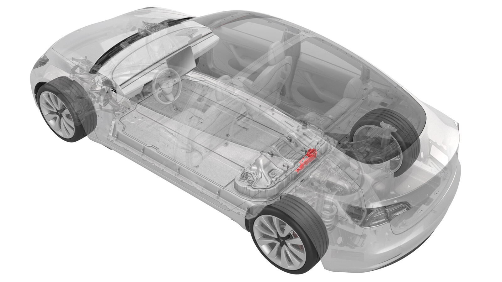
- Retirez le sectionneur de batterie pyrotechnique. Voir Sectionneur de batterie pyrotechnique (retirez et remplacez).
-
Raise the high voltage controller, release the clips that attach the fuse access insulator to the RH ancillary bay bus cover, and remove the insulator.
-
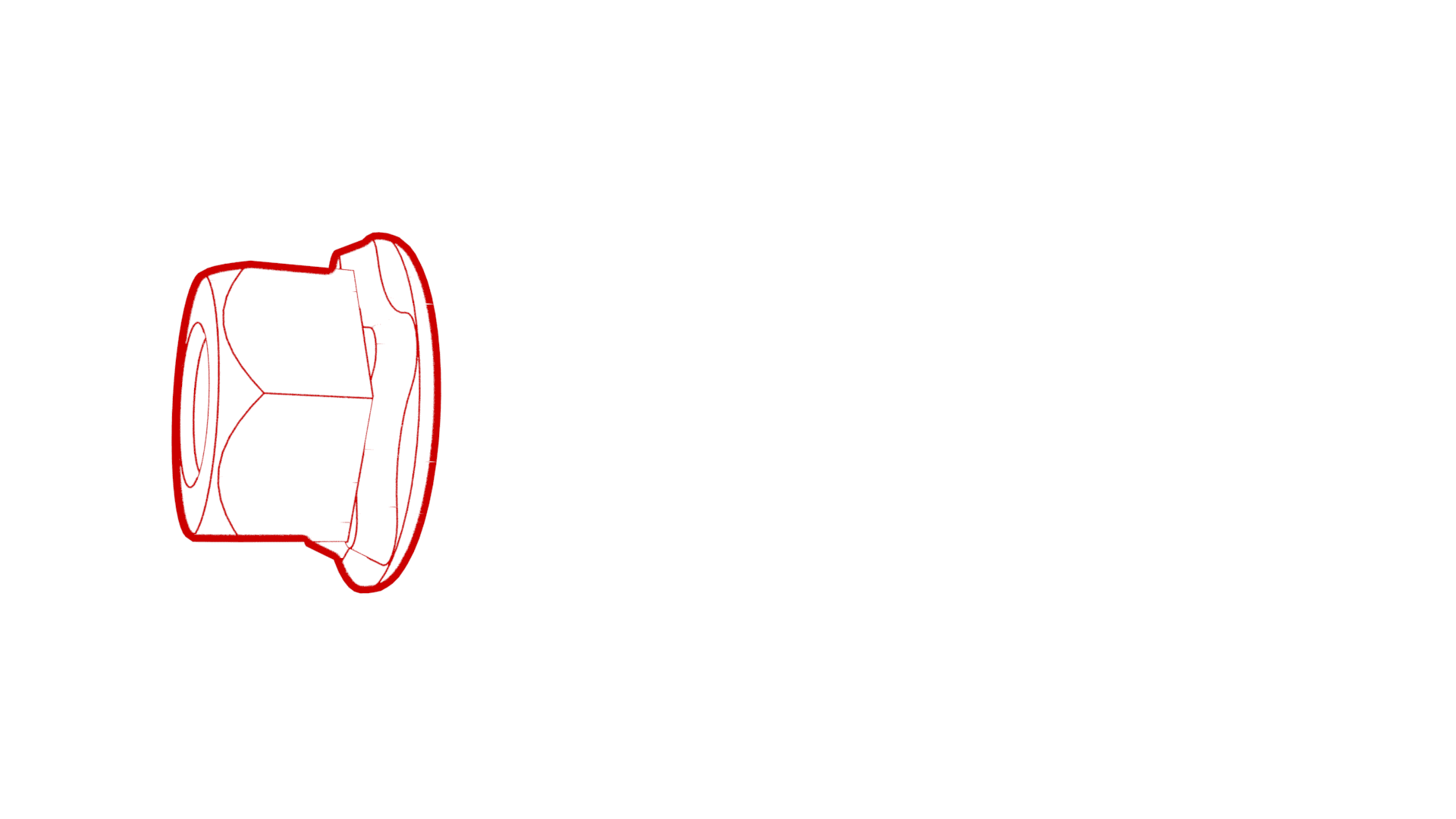
Remove and discard the nuts that attach the A/C compressor fuse to the RH ancillary bay bus and remove the fuse.
Installer
- Perform a zero adjust of the Hioki resistance meter in preparation to measure resistances later in this procedure. See Compteur de résistance (réglage zéro).
-
Install the A/C compressor
fuse to the RH ancillary bay bus, and then install new nuts to attach the fuse
to the bus.
 4.5 Nm (3.3 lbs-ft)
 -
Use the Hioki resistance meter to measure the resistance at the HV joint between the ancillary bay bus and the LH side of the A/C compressor fuse body .
NoteThe maximum acceptable resistance is 0.105 mΩ (105 μΩ). There is too much resistance in the High Voltage joint. Remove the fastener, clean areas with isopropyl alcohol, install fastener back and test again
Figure 1. Generic Measurement - Actual busbars and fasteners might appear different -
Use the Hioki resistance meter to measure the resistance at the HV joint between the RH side of the A/C compressor fuse and the respective ring terminal plating.
NoteThe maximum acceptable resistance is 0.145 mΩ (145 μΩ). There is too much resistance in the High Voltage joint. Remove the fastener, clean areas with isopropyl alcohol, install fastener back and test again
Figure 2. Generic Measurement - Actual busbars and fasteners might appear different -
Install the fuse access insulator on the RH ancillary bay bus cover, fasten the clips that attach the insulator to the cover, and lower the high voltage controller.
- Mesurez la tension à travers les points de montage de déconnexion de la batterie pyrotechnique puis installez la déconnexion de la batterie pyrotechnique Voir Sectionneur de batterie pyrotechnique (retirez et remplacez).