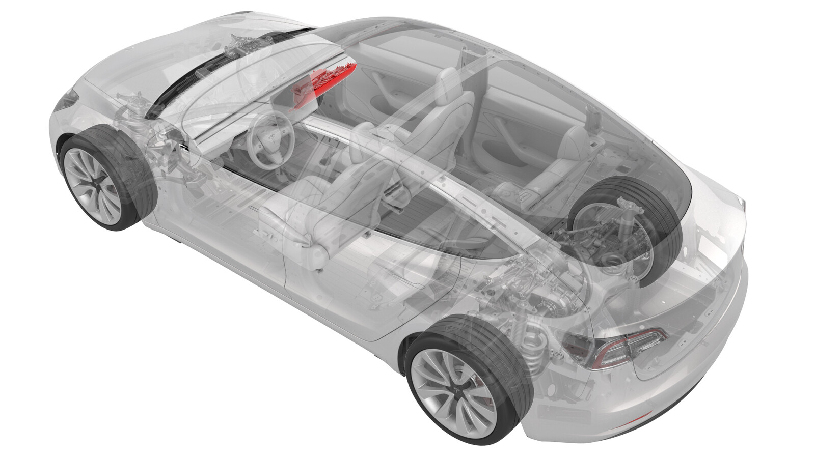
Boîte à gants - sans coussins gonflables pour les genoux (retirez et remplacez)
 Code de correction
14051012 0.24
REMARQUE : À moins d’indications explicites contraires dans la procédure, le code de correction et le temps forfaitaire ci-dessus représentent tout le travail à être fait pour cette procédure, notamment les procédures connexes. N’appliquez pas plusieurs codes de correction à la fois, à moins qu’il vous soit explicitement indiqué de le faire.
REMARQUE : Consultez Temps forfaitaires pour en apprendre plus à propos des temps forfaitaires et de leur création. Vous pouvez transmettre par courriel vos commentaires relatifs aux valeurs des temps forfaitaires à l'adresse ServiceManualFeedback@tesla.com.
REMARQUE : Consultez Protection individuelle pour vous assurer de porter l’équipement de protection individuelle adéquat lors vous effectuez la procédure ci-dessous. Voir Précautions ergonomiques pour consulter les pratiques de travail sécuritaires et saines.
Retirer
- Remove and secure the customer's belongings from the glove box, if needed.
- Remove the LH and RH instrument panel end caps. See Capuchons d’extrémité - tableau de bord - gauche (retirez et remplacez).
- Remove the LH and RH air wave end caps. See Capuchons d’extrémité - onde d’air - gauche (retirez et remplacez).
- Remove the RH middle A-pillar trim. See Garniture - montant avant - milieu - gauche (retirez et remplacez).
- Remove the RH lower A-pillar trim. See Garniture - montant avant - inférieure - gauche (retirez et remplacez).
- Remove the passenger footwell cover. See Couvercle - espace pour les jambes - passager (conduite à gauche) (retirez et remplacez).
- Remove the main instrument panel decor trim. See Garniture décorative - tableau de bord - principal (retrait et remplacement).
- Open the glove box.
-
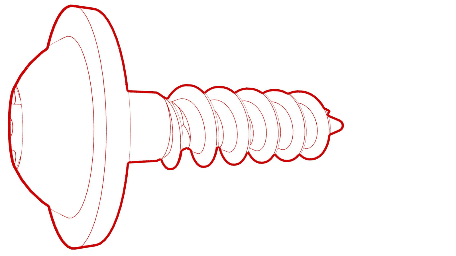
Remove the screws that attach the glove box to the IP carrier.
NoteOne screw may be inside the glove box and not visible in the following image.
-
Release the clips that attach the glove box to the IP carrier.
-
Disconnect the electrical
harness from the glove box solenoid connector, the damper connector, and the
puddle light connector.
Note2 of the electrical connectors are accessed from the bottom of the instrument panel.
-
Remove the glove box from the vehicle.
Installer
-
Bring the glove box into the vehicle, and then connect the electrical harness to the glove box solenoid connector, the damper connector, and the puddle light connector.
Note2 of the electrical connectors are accessed from the bottom of the instrument panel.CAUTIONRoute the electrical harness from the puddle lamp forward of the divider at the linkages.
- Make sure that the glove box damper pin is fully seated, and not to bump the glove box damper when installing the glove box.
-
Fasten the clips that attach the glove box to the IP carrier.
-
Install the screws that attach the glove box to the IP carrier.
 2.3 Nm (1.7 lbs-ft)
 - close the glove box.
- Install the main instrument panel decor trim. See Garniture décorative - tableau de bord - principal (retrait et remplacement).
- Install the passenger footwell cover. See Couvercle - espace pour les jambes - passager (conduite à gauche) (retirez et remplacez).
- Install the RH lower A-pillar trim. See Garniture - montant avant - inférieure - gauche (retirez et remplacez).
- Install the RH middle A-pillar trim. See Garniture - montant avant - milieu - gauche (retirez et remplacez).
- Install the LH and RH air wave end caps. See Capuchons d’extrémité - onde d’air - gauche (retirez et remplacez).
- Install the LH and RH instrument panel end caps. See Capuchons d’extrémité - tableau de bord - gauche (retirez et remplacez).
- Verify that the glove box opens normally through the touchscreen.
- If removed earlier, put the customer's belongings back into the glove box.