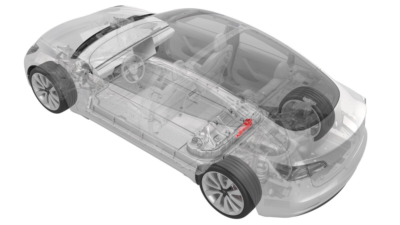
Fusible - Chauffage de l'habitacle - Batterie HT (batterie sur la table) (installez)
 Code de correction
16304026 0.10
REMARQUE : À moins d’indications explicites contraires dans la procédure, le code de correction et le temps forfaitaire ci-dessus représentent tout le travail à être fait pour cette procédure, notamment les procédures connexes. N’appliquez pas plusieurs codes de correction à la fois, à moins qu’il vous soit explicitement indiqué de le faire.
REMARQUE : Consultez Temps forfaitaires pour en apprendre plus à propos des temps forfaitaires et de leur création. Vous pouvez transmettre par courriel vos commentaires relatifs aux valeurs des temps forfaitaires à l'adresse ServiceManualFeedback@tesla.com.
REMARQUE : Consultez Protection individuelle pour vous assurer de porter l’équipement de protection individuelle adéquat lors vous effectuez la procédure ci-dessous. Voir Précautions ergonomiques pour consulter les pratiques de travail sécuritaires et saines.
Équipement :
- 1057602-00-A Clé à rochet, carré cond. 1/4 po, isolé haute tension
- 1057603-00-A Barre rallonge, Wobble, cond. 1/4 po, isolé haute tension
- 1057604-00-A Douille, carré cond. 1/4 po, 8 mm, isolé haute tension
- 1057607-00-A Aimant, flexible, isolé haute tension, 18 po
- 1127845-00-A Ass., couverture entretien, Penthouse, Model 3
- 1076927-00-A Résistivimètre, microohm, Hioki RM 3548
Seuls les techniciens qui ont complété tous les cours de la certification requis sont autorisés à effectuer cette procédure. Tesla recommande aux techniciens fournisseurs de service tiers de suivre la formation équivalente avant d'exécuter cette procédure. Pour obtenir plus d'information sur les exigences pour les techniciens Tesla ou les descriptions à ce sujet pour les tiers, consultez les exigences pour la certification HT. Portez toujours un équipement de protection personnelle et des gants isolants haute tension ayant un classement minimal de 0 (1000 volts) avant de manipuler un câble, une barre omnibus ou des raccords haute tension. Se référer à Tech Note TN-15-92-003, Mises en garde relatives à la haute tension
pour des informations supplémentaires sur la sécurité.
Installer
- Effectuez un réglage à zéro du compteur de résistance Hioki en préparation pour une mesure des résistances, plus tard dans cette procédure. Voir Compteur de résistance (réglage zéro),
- Retirez le sectionneur de batterie pyrotechnique. Voir Sectionneur de batterie pyrotechnique (retirez et remplacez).
-
Soulever le contrôleur haute tension, dégager les attaches qui fixent l'isolateur d'accès aux fusibles au couvercle du bus de la baie auxiliaire droite, et retirer l'isolateur.
-
Installer le fusible de chauffage PTC sur le bus de la baie auxiliaire droite, puis installer de nouveaux écrous pour fixer le fusible au bus.
 4.5 Nm (3.3 lbs-ft)
 -
Utiliser le compteur de résistance Hioki pour mesurer la résistance au niveau de la jonction HT entre le bus de la baie auxiliaire et le côté gauche du corps du fusible de l'élément chauffant CTP.
RemarqueLa résistance maximale acceptable est de 0,105 mΩ (105 μΩ). Il y a trop de résistance dans le joint haute tension. Retirez l'attache, nettoyez les zones avec de l'alcool isopropylique, remettez l'attache et testez à nouveau
Figure 1. Mesure générique - Les barres omnibus et les fixations réelles peuvent sembler différentes -
Utilisez le résistivimètre Hioki pour mesurer la résistance au niveau du joint haute tension entre le côté droit du fusible de chauffage et le placage de la borne à anneau respectif.
RemarqueLa résistance maximale acceptable est de 0,145 mΩ (145 μΩ). Il y a trop de résistance dans le joint haute tension. Retirez l'attache, nettoyez les zones avec de l'alcool isopropylique, remettez l'attache et testez à nouveau
Figure 2. Mesure générique - Les barres omnibus et les fixations réelles peuvent sembler différentes -
Installer l'isolateur d'accès aux fusibles sur le couvercle du bus de la baie auxiliaire droite, fixer les clips qui attachent l'isolateur au couvercle et abaisser le contrôleur haute tension.
- Mesurez la tension à travers les points de montage de déconnexion de la batterie pyrotechnique puis installez la déconnexion de la batterie pyrotechnique Voir Sectionneur de batterie pyrotechnique (retirez et remplacez).
- Retournez à la procédure qui demandait l'installation du fusible du chauffage de l'habitacle.