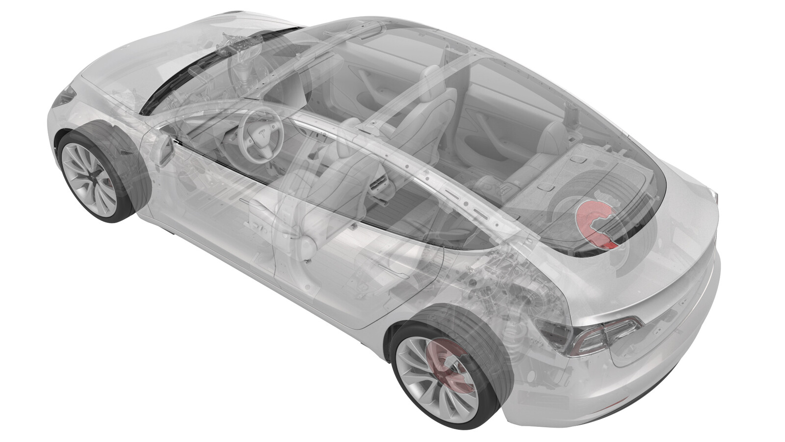
Écran de protection - poussière - frein - arrière - gauche et droit (adaptez)
 Code de correction
33011806 0.60
REMARQUE : À moins d’indications explicites contraires dans la procédure, le code de correction et le temps forfaitaire ci-dessus représentent tout le travail à être fait pour cette procédure, notamment les procédures connexes. N’appliquez pas plusieurs codes de correction à la fois, à moins qu’il vous soit explicitement indiqué de le faire.
REMARQUE : Consultez Temps forfaitaires pour en apprendre plus à propos des temps forfaitaires et de leur création. Vous pouvez transmettre par courriel vos commentaires relatifs aux valeurs des temps forfaitaires à l'adresse ServiceManualFeedback@tesla.com.
REMARQUE : Consultez Protection individuelle pour vous assurer de porter l’équipement de protection individuelle adéquat lors vous effectuez la procédure ci-dessous. Voir Précautions ergonomiques pour consulter les pratiques de travail sécuritaires et saines.
- 2024-05-28: Updated EPB Service Mode reference.
Équipement :
- 1062500-00-A Carte de visionnement de champ magnétique
- 1096075-00-A Outil, extracteur moyeu, hydraulique
Retirer
- Remove any wheel caps or covers, and then loosen the LH rear wheel lug nuts. Do not remove the wheel at this time. See Ensemble de roue (retrait et installation).
-
Loosen the LH rear drive unit halfshaft nut.
- Raise and support the vehicle. See Soulever le véhicule - pont élévateur à 2 poteaux.
- Placez le véhicule en Mode d’entretien du frein de stationnement électrique (EPB). Voir Frein de stationnement - étrier - arrière - gauche (relâcher)
- Remove the LH rear wheel. See Ensemble de roue (retrait et installation).
-
Remove and discard the LH rear drive unit halfshaft nut.
- Remove the LH rear brake rotor. See Disque de frein - arrière - gauche (retirez et remplacez).
-
Remove the bolts that attach the LH rear brake dust shield to the knuckle, and then remove the dust shield from the vehicle.
- Position the hub puller tool on the LH rear wheel studs, and then hand-tighten the wheel lug nuts (x5).
-
Use the hub puller to separate the halfshaft from the hub splines.
TIpWhile holding the hub in position, turn the hydraulic hub puller tool handle clockwise to separate the LH rear drive unit halfshaft from the hub splines.
-
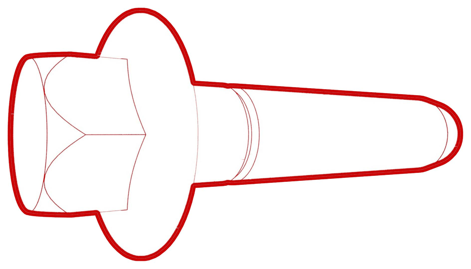
Remove and discard the bolts that attach the LH rear hub to the knuckle, and then remove the hub from the vehicle.
Figure 1. Halfshaft hidden for clarity -
Repeat steps 1 to 11 on the RH side of the vehicle.
Installer
-
Install the bolts that
attach the LH rear brake dust shield to the knuckle.
 8 Nm (5.9 lbs-ft)
 - Use a magnetic field viewing card to check the LH rear hub's tone ring.
-
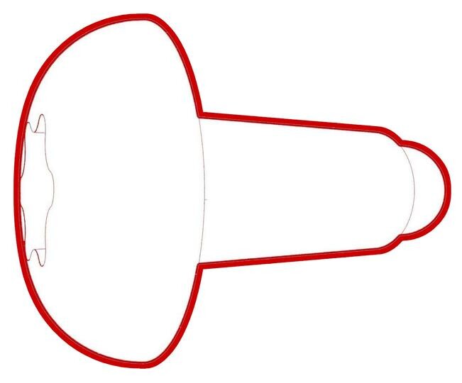
Apply approximately 1 gram of Molykote M-77 Lubricant Paste only to the hub mating face on the outboard side of the LH rear drive unit halfshaft.
CAUTIONDo not apply any lubricant to the halfshaft splines. If lubricant is mistakenly applied, wipe the splines clean with a shop towel.
Figure 2. Lubricate the area highlighted red -
Position the LH rear drive
unit halfshaft in the LH rear hub splines, and then install the new bolts
that attach the hub to the knuckle.
 78 Nm (57.5 lbs-ft)
Figure 3. Halfshaft hidden for clarity - Hand-tighten a new rear drive unit halfshaft nut on the LH halfshaft.
- Install the LH rear brake rotor, but do not perform any road tests. See Disque de frein - arrière - gauche (retirez et remplacez).
- Position the LH rear wheel on the vehicle, and then hand-tighten the LH rear wheel lug nuts.
- Repeat steps 1 to 7 on the RH side of the vehicle.
- Lower the vehicle, and then shift the vehicle into Park (this will disable EPB Service Mode).
- Tighten LH and RH rear wheel lug nuts. See Ensemble de roue (retrait et installation).
-
Tighten the LH and RH rear
drive unit halfshaft nuts.
 300 Nm (221.2 lbs-ft)
 - Install any wheel caps or covers that were removed.
Spécifications de couple
| Description | Valeur de couple | Réutiliser/remplacer | Remarques |
|---|---|---|---|
| Tôle de protection du frein arrière gauche à la fusée |
 8 Nm (5.9 lbs-ft) |
Remplacer | |
| Moyeu à la fusée |
 78 Nm (57.5 lbs-ft) |
Réutiliser | |
| Écrous de demi-arbre de l’unité d’entraînement arrière de gauche et de droite |
 300 Nm (221.2 lbs-ft) |
Réutiliser |