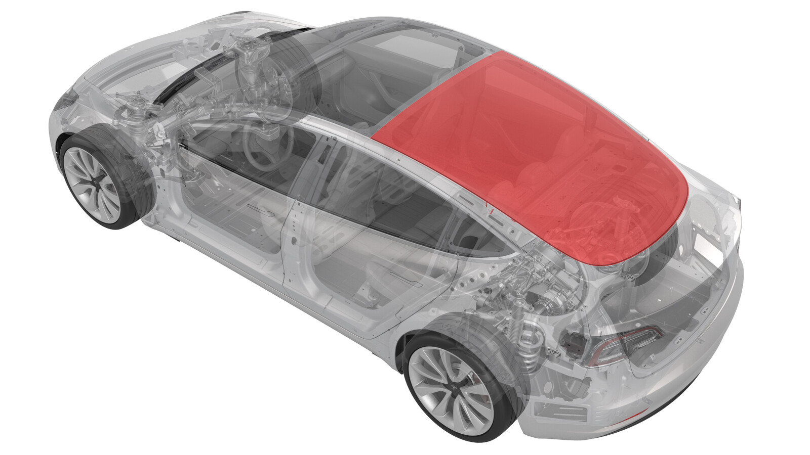
Verre - Lunette arrière (modèle pompe à chaleur) (Retirer et remplacer)
 Code de correction
10204112 1.02
REMARQUE : À moins d’indications explicites contraires dans la procédure, le code de correction et le temps forfaitaire ci-dessus représentent tout le travail à être fait pour cette procédure, notamment les procédures connexes. N’appliquez pas plusieurs codes de correction à la fois, à moins qu’il vous soit explicitement indiqué de le faire.
REMARQUE : Consultez Temps forfaitaires pour en apprendre plus à propos des temps forfaitaires et de leur création.
REMARQUE : Consultez Protection individuelle pour vous assurer de porter l’équipement de protection individuelle adéquat lors vous effectuez la procédure ci-dessous. REMARQUE : Voir Précautions ergonomiques pour consulter les pratiques de travail sécuritaires et saines.
Code de correction
10204112 1.02
REMARQUE : À moins d’indications explicites contraires dans la procédure, le code de correction et le temps forfaitaire ci-dessus représentent tout le travail à être fait pour cette procédure, notamment les procédures connexes. N’appliquez pas plusieurs codes de correction à la fois, à moins qu’il vous soit explicitement indiqué de le faire.
REMARQUE : Consultez Temps forfaitaires pour en apprendre plus à propos des temps forfaitaires et de leur création.
REMARQUE : Consultez Protection individuelle pour vous assurer de porter l’équipement de protection individuelle adéquat lors vous effectuez la procédure ci-dessous. REMARQUE : Voir Précautions ergonomiques pour consulter les pratiques de travail sécuritaires et saines.
- 2024-12-10: Ajout d'un nouvel avertissement concernant les Exigences du service d’inspection de la vitre avant l’installation.
- Le 4 août 2023 : Ajout de l'étape de vérification de l'espace et de l'affleurement en vous référant aux spécifications CVIS.
Équipement :
- Marteau à panne ronde : 115198-00-A
- Égalisateur Python : 1080596-00-A
- Banc portatif : 1054720-00-A
- Couteau à lame rétractable : 1082497-00-A
- Sacs de ballast : 1145158-00-A
- Poignées à double ventouse : 1080599-00-A
- Outil de mesure des affleurements et dégagements : 1588904-00-A
- Pistolet à calfeutrer et à coller : 1080593-00-A
Retirer
-
Ouvrez toutes les portes et abaissez les fenêtres.
RemarqueVerrouillez les portes arrière pour prévenir toute fermeture accidentelle.
- Avancez complètement les deux sièges.
- Libérez les attaches qui retiennent les caches-vis aux crochets à vêtements arrière des côtés gauche et droit.
-
Retirez les vis qui retiennent les crochets à vêtements côtés gauche et droit à la carrosserie.
- Retirez la garniture de l'étagère à colis. Voir Garniture - étagère à colis (retirez et remplacez).
-
Relâchez les attaches (x4) qui fixent l'extrémité arrière de la garniture de toit à la carrosserie.
RemarqueAu besoin, utilisez un ballonnet entre la garniture de toit et la carrosserie pour offrir un dégagement supplémentaire.ATTENTIONVeillez à ne pas endommager la garniture de toit.
-
Débranchez le connecteur du faisceau électrique de rétroéclairage de l'amplificateur d'antenne du côté du montant arrière du côté gauche.
-
Débranchez le connecteur de l'antenne du filtre antiparasite situé sur le côté gauche du véhicule.
-
Dégagez le faisceau de barre omnibus de lunette arrière de gauche de la carrosserie.
-
Débranchez le connecteur de l'antenne du filtre antiparasite 12 V situé sur le côté droit du véhicule.
-
Dégagez le faisceau de barre omnibus de lunette arrière du côté droit de la carrosserie.
-
Débranchez le connecteur du faisceau électrique de lunette arrière du syntonisateur sur le montant C du côté droit.
- Ouvrez le coffre.
-
Retirez et jetez le joint d'étanchéité arrière de la vitre de lunette arrière.
RemarqueLa nouvelle vitre de lunette arrière est dotée d'un nouveau joint arrière déjà installé.
-
Retirez et mettez au rebut le joint avant de la vitre de lunette arrière.
RemarqueLa nouvelle vitre de lunette arrière est dotée d'un nouveau joint arrière déjà installé.
- Appliquez un ruban de masquage à l'extérieur des montants de toit gauche et droit pour protéger la peinture de tout dommage.
- Insérez l'outil d'engagement à partir de l'intérieur du véhicule à travers le cordon adhésif qui se trouve dans la partie inférieure de la lunette arrière.
- Insérez l'extrémité du fil de nylon à travers l'œillet de l'outil d'engagement et tirez-le à l'intérieur du véhicule.
- Nettoyez la vitre de la lunette arrière du toit en verre à l'alcool isopropylique.
- Positionnez l'ensemble de la coupelle Python au centre de la lunette arrière.
- Faites un nœud à l'extrémité de la corde de nylon et insérez la boucle à travers la languette d'ancrage de la coupelle python.
- Placez l'unité de glissement sur la vitre de lunette arrière.
-
Tirez le fil de nylon de la coupelle autour de l'unité de glissement de la lunette arrière.
RemarquePivotez la poignée de la coupelle Python jusqu'à ce que la corde de nylon soit serrée.
- Positionnez le fil de nylon autour de la lunette arrière à partir de l'extérieur du véhicule.
- Insérez l'outil de démarrage à travers le boudin adhésif qui se trouve à proximité de la lunette arrière.
- Tirez la corde de nylon à travers la lunette arrière jusqu'à l'intérieur du véhicule.
- Faites un nœud d'arrêt à l'extrémité libre de la corde de nylon, puis insérez-la dans la fente crantée de la coupelle Python.
-
Pivotez la barre de la poignée de la coupelle Python de façon à ce que le rembobinage de la corde de nylon coupe l'uréthane qui fixe le verre de la lunette arrière à la carrosserie. Coupez en pratiquant un déplacement antihoraire sur le dessus de la vitre de lunette arrière vers le côté inférieur du montant C gauche. Revenez au point de départ selon un déplacement horaire et continuez au-delà du bas de la lunette arrière vers le côté inférieur du montant C gauche.
ATTENTIONSoyez prudent lorsque vous effectuez une tâche près de la garniture de toit.
- Retirez l'égalisateur Python de la lunette arrière.
- Retirez le fil de l’outil d’engagement et retirez l’outil de l’uréthane.
- Fixez des ventouses sur les côtés gauche et droit de la vitre de lunette arrière.
- Avec l'aide d'un assistant, retirez la vitre de lunette arrière du véhicule.
-
Utilisez une lame de rasoir pour éliminer l'ancien uréthane de la bride de pare-brise du véhicule.
- Nettoyez le trajet d'uréthane sur le véhicule à l'aide d'un tampon d’alcool isopropylique.
Installer
- Fixez des ventouses sur les côtés gauche et droit de la vitre de lunette arrière.
- Avec l'aide d'un assistant, placez la vitre de lunette arrière sur le véhicule pour effectuer un préessayage et notez les endroits où les coussinets doivent être ajustés.
- Vérifiez que l'espace et l'affleurement avec toutes les zones environnantes sont conformes aux spécifications CVIS et ajustez si nécessaire.
-
Au besoin, effectuez un ajustement des coussinets.
- Avec l'aide d'un assistant, retirez la vitre de lunette arrière et placez-la sur un support.
- Nettoyez le trajet d'uréthane sur le véhicule à l'aide de tampons d’alcool isopropylique. Laissez sécher la surface avant de passer à l’étape suivante.
-
Appliquer un apprêt à l'uréthane :
- Appliquez un apprêt à l'uréthane sur le véhicule le long du trajet d'uréthane et dans les zones qui ont été endommagées durant le retrait de la vitre de lunette arrière.
- Appliquez l'apprêt à l'uréthane sur la vitre de lunette arrière le long du trajet d'uréthane.
RemarqueLaissez l'apprêt sécher pendant au moins 2 minute avant de continuer. -
Appliquez l'uréthane à la carrosserie en suivant le trajet d'origine.
RemarqueVeillez à appliquez un cordon d'uréthane affichant une section triangulaire d'environ 8 mm de large par 13 mm de haut.
- Avec un assistant, placez la vitre de lunette arrière sur le véhicule.
- Vérifiez l'affleurement et les espaces autour de la vitre de lunette arrière par rapport à la carrosserie avant de l'appuyer complètement.
- Fermez le coffre.
- Appuyez complètement la vitre de lunette arrière, vérifiez l'affleurement et les espaces, et ajustez au besoin.
-
Appliquez un ruban à masquer pour fixer la vitre de lunette arrière à la carrosserie pendant le séchage de l'uréthane.
RemarquePour connaître le temps de séchage de l'uréthane, suivez les recommandations du fabricant de l'uréthane.
- Retirez les ventouses de la lunette.
- Installez l'extrémité arrière de la garniture de toit sur la carrosserie.
-
Branchez le connecteur du faisceau électrique de lunette arrière au syntonisateur sur le montant C du côté droit.
-
Fixez le faisceau de barre omnibus de lunette arrière de droite sur la carrosserie.
-
Branchez le connecteur de l'antenne du filtre antiparasite 12 V situé sur le côté droit du véhicule.
-
Fixez le faisceau de barre omnibus de lunette arrière de gauche sur la carrosserie.
-
Branchez le connecteur de l'antenne du filtre antiparasite situé sur le côté gauche du véhicule.
-
Branchez le connecteur du faisceau de lunette arrière à l'amplificateur d'antenne.
- Installez la garniture de l'étagère à colis. Voir Garniture - étagère à colis (retirez et remplacez).
-
Posez les vis qui retiennent les crochets à manteau de gauche et de droite à la carrosserie.
 2.5 Nm (1.8 lbs-ft)
 - Serrez les pinces qui retiennent les caches-vis aux côtés gauche et droit des crochets à vêtements.
-
Si le véhicule a des alertes relatives au dégivreur arrière, effectuez ces étapes supplémentaires pour réactiver le dégivreur arrière.
- Branchez un ordinateur portable doté du logiciel Toolbox 3 au véhicule . Voir Toolbox (connecter et déconnecter).
- Dans Toolbox, cliquez sur l'onglet Actions, puis saisissez « Defrost » (dégivrage) dans le champ de recherche, cliquez sur PROC_VCRIGHT_REAR_DEFROST-RE-ENABLEvia Service Mode:Closures ➜ Windows ➜ Re-Enablevia Toolbox:(link), cliquez sur Exécuter et laissez la routine se terminer.
- Débranchez l’ordinateur portable du véhicule. Voir Toolbox (connecter et déconnecter).
- Relevez toutes les fenêtres et fermez toutes les portes.
-
Retirez le ruban de masquage une fois l'uréthane sèche.
ATTENTIONNe conduisez pas le véhicule avant que le temps de remise en service minimal recommandé par le fabricant de l’adhésif ne se soit écoulé. Dow Betaseal Express a un temps de remise en service minimal de 1 heure lorsque la température est de 0 ˚F (-18 ˚C) ou plus. Au besoin, laissez le ruban adhésif qui applique une pression sur la vitre et demandez au client de le retirer après 24 heures. De plus, indiquez au client d’éviter de conduire à haute vitesse et de rouler sur des dos d’âne pendant les prochaines 24 heures.