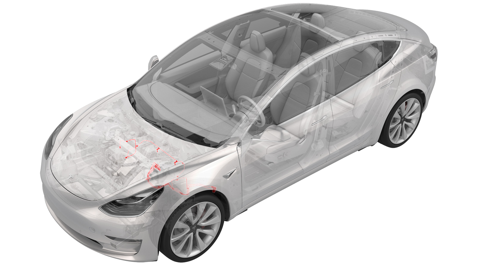
Conduites de frein – ensemble 4 tubes – entre ABS et les pneus (moteur double) (retrait et remplacement)
 Code de correction
330339524.62
REMARQUE : À moins d’indications explicites contraires dans la procédure, le code de correction et le temps forfaitaire ci-dessus représentent tout le travail à être fait pour cette procédure, notamment les procédures connexes. N’appliquez pas plusieurs codes de correction à la fois, à moins qu’il vous soit explicitement indiqué de le faire.
REMARQUE : Consultez Temps forfaitaires pour en apprendre plus à propos des temps forfaitaires et de leur création. Vous pouvez transmettre par courriel vos commentaires relatifs aux valeurs des temps forfaitaires à l'adresse ServiceManualFeedback@tesla.com.
REMARQUE : Consultez Protection individuelle pour vous assurer de porter l’équipement de protection individuelle adéquat lors vous effectuez la procédure ci-dessous. Voir Précautions ergonomiques pour consulter les pratiques de travail sécuritaires et saines.
Le liquide de frein dissout la peinture. Ayez à portée de main des serviettes propres et beaucoup d’eau afin de nettoyer tout déversement de liquide de frein sur les surfaces peintes, le cas échéant.
Jetez le liquide de frein usé d’une manière qui respecte les codes environnementaux locaux.
- Remove the front subframe. See Ensemble de sous-châssis - avant (moteur double) (retirez et installez).
- Remove the 12V battery bracket. See Support - batterie 12 V (moteur double) (retirez et remplacez).
-
Remove the bolts (x2) that attach the ground leads (G098 and G099) to the LH side of the body.
RemarqueDiscard thread-cutting tri-lobular bolts after removal. If equipped with new bolts (1447438-00-A), the bolts can be reused.
-
Release the white harness clip from the body.
-
Release the black harness clip from the body.
-
Remove the front harness clip from the LH frame rail area.
-
Disconnect the ground connector (G011) from the LH frame rail area.
-
Move the LH side of the front harness aside for access.
-
Disconnect the ABS modulator connector.
RemarqueDisengage locking tab and pull up on the connector to release.
-
Release the front harness clips (x2) at the LH frame rail area.
- Placez le dispositif de vidange d’huile sous l’unité ABS.
-
Enlevez les écrous de la conduite de frein de l’unité, et laissez le liquide se vidanger.
-
Remove the front brake line bundle clip at the LH front rail area.
-
Remove the RH front brake line from the front brake line bundle clip at the LH front rail area.
- Remove the oil drain container from underneath the vehicle.
- Partially raise the vehicle.
-
Remove the thermal beam hose clips (x2) from the body.
- Placez le dispositif de vidange d’huile sous la boîte de jonction de la conduite de frein avant.
-
Enlevez les écrous de la conduite de frein de la boîte de jonction, et laissez le liquide se vidanger.
-
Remove the black clip from the LH front junction block.
-
Release the brake lines from the LH front junction block.
- Placez le dispositif de vidange d’huile sous le boyau de liquide de frein avant gauche.
-
Retirez l’écrou de la conduite de frein du boyau de frein au support de flexible, et laissez le liquide se vidanger.
-
Remove the LH front brake line clip from the body.
- Placez le dispositif de vidange d’huile sous le boyau de liquide de frein avant droit.
-
Retirez l’écrou de la conduite de frein du boyau de frein au support de flexible, et laissez le liquide se vidanger.
-
Remove the RH front brake line clips (x2) from the body.
- Fully raise the vehicle.
-
Release the coolant hose clip on the LH fender.
-
Remove the front brake line bundle clip from the LH body rail area.
-
Remove the LH front side 3 bundle brake lines from the vehicle.
RemarqueRoute the front brake line bundle out of steering column area, then route it through LH front wheel liner and front subframe area.
-
Release the clips (x3) that attach the 12V harness to the body.
-
Release the clips (x7) that attach the HV cables to the body.
-
Release the clips (x2) that attach the coolant manifold line from the body.
-
Release the clips (x4) that attach the coolant hoses to the body.
-
Release the clip that attaches the coolant hose to the RH side of the body.
-
Remove the clips (x5) that attach the RH front brake line to the body.
-
Remove the RH front brake line from the vehicle.
RemarqueRoute the brake line out of steering column area, then move it towards the RH side, and the remove it out between the front subframe area.
Installer
- Remove the RH front brake line from the new front 4 tube brake bundle.
-
Position the RH front brake line to vehicle for installation.
RemarqueRoute the RH front brake line through the front subframe area out toward the RH front wheel liner area, then route it to LH frame rail area.
-
Install the clips (x5) that attach the RH front brake line to the body.
-
Install the clip that attaches the RH side coolant hose to the body.
-
Install the clips (x4) that attach the coolant hoses to the body.
-
Install the clips (x2) that attach the coolant manifold line to the body.
-
Install the clips (x7) that attach the HV cables to the body.
-
Install the clips (x3) that attach the 12V harness to the body.
-
Install the left side 3 tube bundle to the vehicle.
RemarqueRoute the brake line bundle through the LH front wheel liner and front subframe area, then route it to LH frame rail area.
-
Install the clip that attaches the coolant hose to the LH fender.
-
Install the clip that attaches the front brake line bundle to LH body rail area.
- Partially lower the vehicle.
-
Install the RH front brake line into the brake hose at the jounce hose bracket, and then use a crowfoot extension to install the brake line tube nut into the brake hose.
 16 Nm (11.8 lbs-ft)
 -
Install the RH front brake line clips (2) to the body.
-
Insérez la conduite de frein dans le boyau de frein au support flexible, puis utilisez une rallonge à pied de biche pour installer l’écrou de la conduite de frein dans le boyau de frein.
 16 Nm (11.8 lbs-ft)
 -
Install the clip that attaches the LH front brake line clip to body
Remarque1x clip
-
Install the brake lines into the LH front junction block.
-
Install the clip that secures the brake lines at the LH front junction block.
-
Use a crowfoot extension to install the brake line tube nuts into the junction block.
 16 Nm (11.8 lbs-ft)
 -
Install the thermal beam hose clips (x2) to the body.
- Lower the vehicle.
-
Install the RH front brake line to front brake line bundle clip at the LH front rail area.
-
Install the front brake line bundle clip at the LH front rail area.
-
Install the master cylinder brake lines to the 4 tube bundle clip.
-
Insérez les conduites de frein dans l’unité ABS, puis utilisez une rallonge à pied de biche pour installer les écrous de la conduite de frein dans l’unité ABS.
 16 Nm (11.8 lbs-ft)
 -
Re-position the LH side of the front harness to the LH frame rail for installation.
-
Install the front harness clips (x2) at the LH frame rail area.
-
Connect the LH frame rail ground connector (G011).
-
Install the front harness clip to the LH frame rail area.
-
Install the white harness clip to the left front fender.
-
Install the black harness clip to the left front fender.
-
Install the bolts (x2) that attach the grounds leads (G098 and G099) to the body (torque 10 Nm).
RemarqueInstall new bolts if thread-cutting tri-lobular bolts were installed previously. Hand-start bolts at least 6 rotations before applying torque to avoid damaging the weld nut.
-
Install the ABS modulator connector
RemarqueGently push connector downward, then engage locking tab
- Reinstall the 12V battery bracket. See Support - batterie 12 V (moteur double) (retirez et remplacez).
- Install the 12V battery into the vehicle. See 12 V /BT batterie (retirez et remplacez).
- Install the front subframe. See Ensemble de sous-châssis - avant (moteur double) (retirez et installez).
- Connect 12V power. See Alimentation 12 V/BT (déconnectez et connectez).
- Remove the HVAC plenum outer duct. See Plénum - entrée - CVC (retrait et remplacement).
- Perform a coolant air purge. See Système de refroidissement (remplissage partiel et purge).
- Bleed the brakes. See Saignement/vidage de fluide de frein.
- Install the underhood storage unit. See Unité de rangement sous le capot (retirez et remplacez).
- Install the HVAC plenum outer duct. See Plénum - entrée - CVC (retrait et remplacement).
- Install the rear underhood apron. See Tablier sous le capot - arrière (retirez et remplacez).
- Install the front aero shield. See Panneau - écran aérodynamique - avant (retirez et remplacez).
- Install the LH and RH wheel liner. See Doublure d’aile - avant - gauche (retirez et remplacez).
- Install all wheels. See Ensemble de roue (retrait et installation).
- Torque the LH and RH front halfshaft nuts to 300 Nm.
- Perform a 4-wheel alignment check. See Parallélisme des quatre roues (vérification).