Échangeur de chaleur - unité d’entraînement arrière (4DU) (retirez et remplacez)
 Code de correction
40305232 0.66
REMARQUE : À moins d’indications explicites contraires dans la procédure, le code de correction et le temps à taux fixe (FRT) connexe représentent tout le travail à accomplir pour cette procédure, y compris les procédures connexes. N’appliquez pas plusieurs codes de correction à la fois, à moins qu’il vous soit explicitement indiqué de le faire.
REMARQUE : Consultez Temps forfaitaires pour en apprendre plus à propos des temps forfaitaires et de leur création.
REMARQUE : Consultez Protection individuelle pour vous assurer de porter l’équipement de protection individuelle adéquat lors vous effectuez la procédure ci-dessous. REMARQUE : Voir Précautions ergonomiques pour consulter les pratiques de travail sécuritaires et saines.
Code de correction
40305232 0.66
REMARQUE : À moins d’indications explicites contraires dans la procédure, le code de correction et le temps à taux fixe (FRT) connexe représentent tout le travail à accomplir pour cette procédure, y compris les procédures connexes. N’appliquez pas plusieurs codes de correction à la fois, à moins qu’il vous soit explicitement indiqué de le faire.
REMARQUE : Consultez Temps forfaitaires pour en apprendre plus à propos des temps forfaitaires et de leur création.
REMARQUE : Consultez Protection individuelle pour vous assurer de porter l’équipement de protection individuelle adéquat lors vous effectuez la procédure ci-dessous. REMARQUE : Voir Précautions ergonomiques pour consulter les pratiques de travail sécuritaires et saines.
- 2026-09-01: Removed steps to disconnect/connect the LV power and added oil pump low pressure test routine.
- 2024-01-10: Corrected spellings of "exchanger".
Retirer
- Move the vehicle to a 2 post lift. See Soulever le véhicule - pont élévateur à 2 poteaux.
- Open the LH front door and raise the LH front window.
- Enable Service Mode on the touchscreen. See Mode Entretien.
- Unlock the vehicle gateway. See Passerelle (déverrouiller).
-
Access the thermal system routines on the touchscreen: Touch Quick Controls > Service Mode > Diagnostics > Thermal.
RemarqueAuthorize routines by holding the turn signal stalk full up (right hand turn) while applying brake with the key in the vehicle.
-
Touch Start Thermal Fill Drain (Coolant Only) on the touchscreen.
RemarqueTouch the X at the top left of window to close once completed.RemarqueVerify the indicator displays green and the vehicle is ready for the coolant fill/drain.RemarqueThermal "Fill Drain" routine has a 5 hour time limit. After 5 hours, the routine must be performed again.
- Remove the rear underhood apron. See Tablier sous le capot - arrière (retirez et remplacez).
- Remove the cabin intake duct. See Conduit - supérieur - admission de la cabine (retrait et remplacement).
- Remove the rear aero shield panel. See Panneau – bouclier aérodynamique – arrière (retrait et remplacement).
- Drain the gearbox fluid from the rear drive unit. See Liquide de la boîte d’engrenages - unités d’entraînement arrière (4DU) (vidange et remplissage).
-
Position the coolant drain collector underneath the RH rear of the HV battery.
-
Release the clip that attaches the rear drive unit inverter to heat exchanger hose to the rear drive unit heat exchanger.
-
Release the clip, disconnect the rear drive unit inverter to heat exchanger hose from the rear drive unit heat exchanger, immediately plug the heat exchanger fitting, allow the hose to drain, and then plug the hose fitting.
-
Release the clip that attaches the rear drive unit outlet hose to the rear drive unit heat exchanger.
-
Release the clip, disconnect the rear drive unit outlet hose from the rear drive unit heat exchanger, and then immediately plug both fittings.
RemarqueCoolant loss greater than 1 L will require a vacuum fill.
-
Remove the bolts (x2) that attach the rear drive unit heat exchanger to the rear drive unit, and then remove the heat exchanger from the drive unit.
RemarqueUse of the following tool(s) is recommended:
- 4 in extension
- External Torx Plus EP10
- Ratchet/torque wrench
RemarqueConfirm that the O-rings (x2) are not stuck in the rear drive unit.
Installer
-
Apply a light coat of KAF1 oil to the O-rings of the heat exchanger, and then wipe away any excess oil.
-
Install the rear drive unit heat exchanger onto the rear drive unit, and then install the bolts (x2) that attach the heat exchanger to the drive unit.
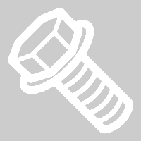 5 Nm (3.7 lbs-ft) +30 deg
 -
Remove the plugs from the fittings, immediately connect the rear drive unit outlet hose to the rear drive unit heat exchanger, fasten the clip, and then perform a Push-Pull-Push check of the fitting.
-
Fasten the clip that attaches the rear drive unit outlet hose to the rear drive unit heat exchanger.
-
Remove the plugs from the fittings, immediately connect the rear drive unit inverter to heat exchanger hose to the rear drive unit heat exchanger, fasten the clip, and then perform a Push-Pull-Push check of the fitting.
-
Fasten the clip that attaches the rear drive unit inverter to heat exchanger hose to the rear drive unit heat exchanger.
-
Remove the coolant drain collector from under the vehicle.
- Refill the rear drive unit with gearbox fluid. See Liquide de la boîte d’engrenages - unités d’entraînement arrière (4DU) (vidange et remplissage).
- Install the mid aero shield panel. See Panneau – bouclier aérodynamique – arrière (retrait et remplacement).
- Lower the vehicle fully.
- Connect a laptop with Toolbox to the vehicle. SeeToolbox (connecter et déconnecter).
- Perform the routine: TEST-SELF_DIR_X_OIL-PUMP-PRESSUREvia Toolbox:(link)
- Disconnect the laptop from the vehicle. SeeToolbox (connecter et déconnecter).
-
Remove the cap from the coolant bottle.
RemarquePerform this step only for heat pump vehicles.
-
Inspect the coolant level and add coolant as necessary to bring the fluid level to the Max line.
RemarqueIf greater than 1 L of coolant was lost during repair, a vacuum fill is required.
- On the vehicle touchscreen, go to , touch Run and allow the routine to complete.
- On the vehicle touchscreen, go to , touch Run and wait for the routine to complete (10 minutes).
-
Add coolant to the reservoir as necessary, and install the reservoir cap.
- Install the cabin intake duct. See Conduit - supérieur - admission de la cabine (retrait et remplacement).
- Install the rear underhood apron. See Tablier sous le capot - arrière (retirez et remplacez).
- Disable Service Mode. See Mode Entretien.
- Raise the LH front window and close the LH front door.
- Remove the vehicle from the 2 post lift. See Soulever le véhicule - pont élévateur à 2 poteaux.